manual printing

Manual Printing: An Overview

Manual printing encompasses diverse hand-printing techniques, including lithography, letterpress, and relief methods like woodcut and engraving.

Historically significant, these processes offer unique artistic expression, experiencing a modern resurgence driven by creative exploration and tactile appeal.

Access to tools empowers engineers, while technological advancements increase accessibility and user-friendliness, impacting the world of manual printing.

Historical Context of Manual Printing

Manual printing boasts a rich history, originating with ancient relief methods – notably woodblock printing in China centuries ago. This foundational technique spread across Asia, eventually reaching Europe, where it significantly impacted early book production.

The development of the printing press by Johannes Gutenberg in the 15th century, while a mechanical advancement, still relied heavily on manual labor for typesetting and operation. Letterpress, a core manual technique, flourished for centuries, shaping communication and knowledge dissemination.

Lithography, emerging in the late 18th century, offered artists a new manual avenue for printmaking, distinct from relief and intaglio. Throughout the 19th and 20th centuries, various manual processes coexisted with emerging technologies, maintaining a dedicated following among artists valuing the handcrafted aesthetic and unique qualities inherent in hand-printing.

The Resurgence of Manual Printmaking

Despite the dominance of digital printing, manual printmaking is experiencing a vibrant revival in the 21st century. This resurgence is fueled by a growing appreciation for the tactile qualities and unique imperfections inherent in hand-printed works.

Artists and designers are increasingly drawn to the directness and creative control offered by techniques like letterpress, woodcut, and monoprinting. Online resources, workshops, and classes are fostering a new generation of practitioners eager to learn these traditional skills.

Furthermore, the integration of digital design tools with manual processes – using digital layouts for letterpress or scanned textures in collage – expands creative possibilities. This blend of old and new attracts artists seeking both artistic depth and contemporary expression, solidifying manual printing’s continued relevance.

Core Manual Printing Techniques

Manual printing fundamentally relies on relief, lithography, and letterpress methods, each offering distinct aesthetic qualities and requiring specialized tools for image transfer and creation.

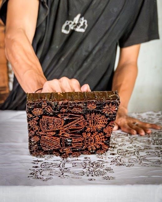
Relief Printing: The Oldest Method

Relief printing stands as the earliest known printing technique, a process where the image to be printed is raised from a surface. This foundational method involves carving away the non-image areas, leaving the design raised to accept ink.

It can be executed using a printing press for consistent pressure or manually, utilizing tools like a barren to transfer the ink. The simplicity and directness of relief printing have made it a cornerstone of artistic expression for centuries.

This technique’s enduring appeal lies in its ability to produce bold, graphic images, and its accessibility allows for experimentation with various materials and approaches. It remains a vital practice in contemporary art.

Woodcut as a Relief Technique

Woodcut is a classic example of relief printing, traditionally employing a wooden block as the matrix. Artists carve away sections of the wood, leaving the desired image raised on the surface. This process demands careful planning, as the image is created in reverse.

Once carved, the block is inked, and then pressed onto paper – either manually using a barren or with a printing press. Woodcut is known for its bold lines and graphic quality, often resulting in striking black and white prints.

Historically significant, woodcut was widely used for book illustrations and prints before more refined techniques emerged. It continues to be valued for its distinctive aesthetic and direct, expressive nature.

Wood Engraving: Detail and Precision

Wood engraving, a refined relief printing technique, differs from woodcut through the use of the end-grain of hardwood, typically boxwood. This allows for significantly finer detail and more precise lines than can be achieved with traditional woodcut.

Artists utilize specialized tools – gravers – to carve into the wood, creating a delicate network of lines that define the image. The process is meticulous and requires considerable skill and patience. Often, wood engraving is mistaken for copperplate engraving (intaglio).

The resulting prints exhibit a remarkable level of detail and tonal variation, making wood engraving ideal for illustrations, portraits, and intricate designs. It flourished in the 19th century and remains a valued art form today.

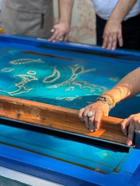
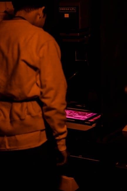
Lithography: Printing from Stone

Lithography, meaning “stone writing,” is a manual printing technique based on the principle that oil and water repel each other. Traditionally, artists draw directly onto a smooth, flat limestone surface with a greasy crayon or tusche.

This creates an image that attracts ink, while the non-greased areas repel it. After treatment with chemicals to fix the image, the stone is dampened with water, and then inked. Paper is then pressed onto the stone, transferring the image.

Lithography allows for a wide range of tonal values and painterly effects, unlike the stark contrasts of some other hand-printing techniques. It became popular in the early 19th century and continues to be practiced by artists today.

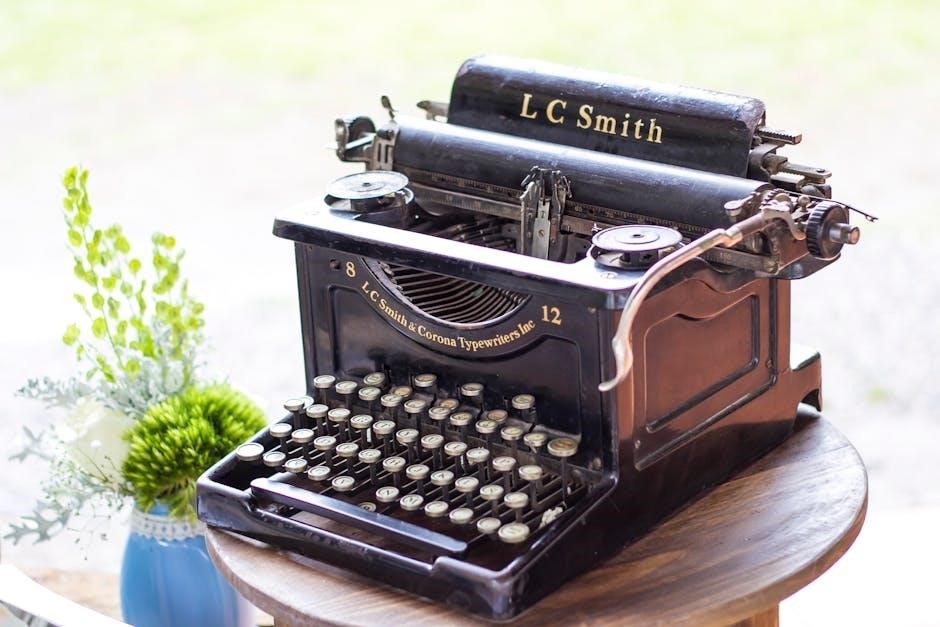
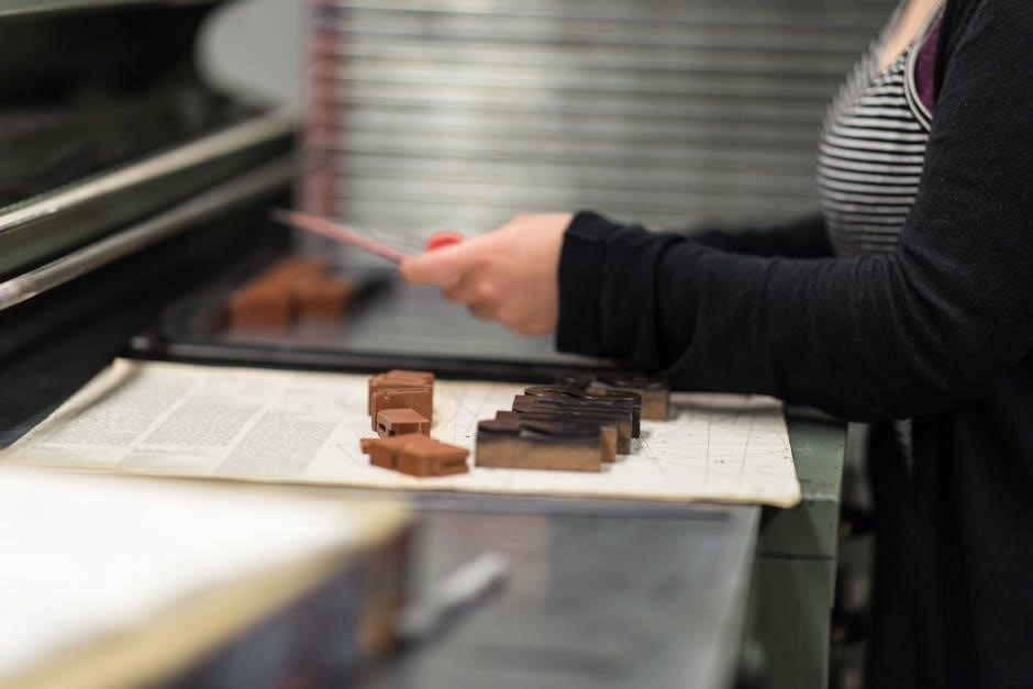
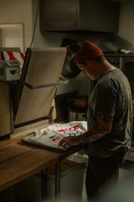
Letterpress: The Art of Impression

Letterpress is a manual printing technique where inked, raised surfaces are pressed into paper, creating a tactile impression. Historically, this involved movable type – individual letters and characters assembled to form words and images.

Today, letterpress often utilizes photopolymer plates created from digital designs. These plates are mounted onto a press, inked with specialized inks, and then pressed firmly onto the paper using significant pressure.

The resulting prints exhibit a distinctive, debossed quality, valued for its luxurious feel and vintage aesthetic. Letterpress is celebrated for its craftsmanship and the unique character it imparts to each impression, making it a favored choice for invitations and artistic prints.

Manual Printing Processes Explained

Manual printing relies on matrix preparation, careful inking application, and consistent pressure to transfer images onto paper, yielding unique, handcrafted results.

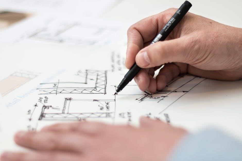
Preparing the Printing Matrix

Preparing the printing matrix is a foundational step in manual printing, varying significantly based on the chosen technique. For relief methods like woodcut or wood engraving, this involves carving the design into a wood block, removing areas that won’t hold ink.

Lithography requires treating a stone or metal plate to create a surface that accepts ink only in the desired areas. Letterpress utilizes meticulously arranged movable type or etched metal plates.

Regardless of the method, the matrix must be carefully prepared to ensure a clean, consistent transfer of the image. This often involves cleaning, surface treatment, and, in some cases, applying protective coatings to prevent unwanted inking or damage. The quality of the matrix directly impacts the final print’s clarity and detail.

Inking the Matrix

Inking the matrix is a crucial stage in manual printing, demanding precision to achieve a quality impression. Traditionally, printing inks are applied using rollers, ensuring an even coating across the prepared surface. The type of ink selected depends on the printing technique; oil-based inks are common for lithography and letterpress, while water-based inks suit some relief methods.

The inking process requires careful control of pressure and ink quantity. Too little ink results in a faint print, while excessive ink can cause blurring or smudging. Skilled printers utilize techniques to distribute the ink uniformly, avoiding voids or build-up.

Consistent inking is paramount for repeatable results and a visually appealing final product, directly influencing the print’s tonal range and vibrancy.

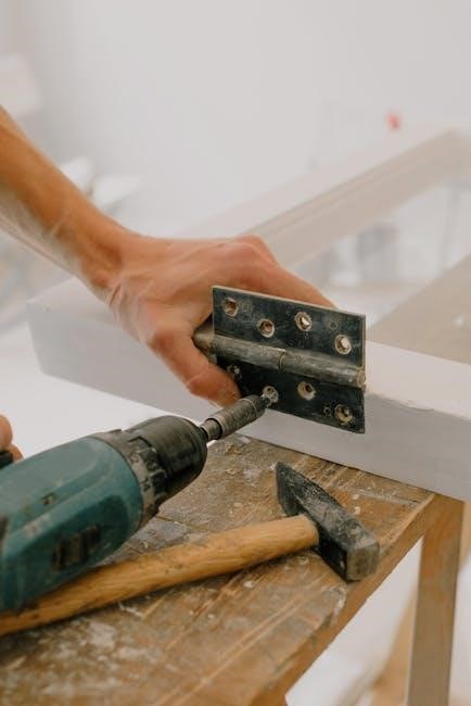
Applying Pressure for Transfer

Applying pressure is the pivotal moment in manual printing where the inked image transfers from the matrix to the chosen substrate, typically paper. This is achieved through various methods, ranging from hand-rubbing for simpler techniques like woodcuts, to utilizing the substantial force of a printing press for letterpress or lithography.

Consistent and even pressure distribution is essential for a clear, well-defined print. Insufficient pressure yields a weak impression, while excessive pressure can damage both the matrix and the paper.

Manual presses allow for precise control over pressure settings, enabling printers to fine-tune the process for optimal results. The choice of paper also impacts pressure requirements; softer papers necessitate gentler application.

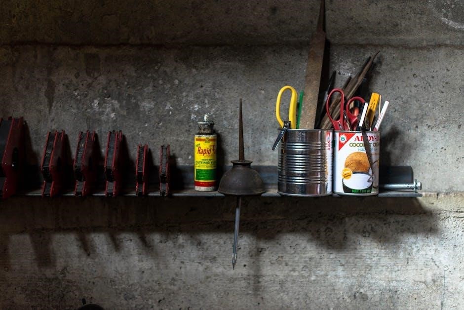
Tools and Materials for Manual Printing

Manual printing requires specialized tools like presses, rollers for inking, and appropriate papers; inks are applied evenly using rollers or pads for optimal results.

Printing Presses (Manual Operation)

Manual printing presses are central to many techniques, offering controlled pressure for transferring ink from the matrix to the paper. These presses range from simple tabletop models ideal for small-scale projects to larger, more robust floor-standing machines capable of handling bigger prints.

Unlike automated presses, manual operation demands physical effort – the printer manually cranks a wheel or lever to apply pressure. This direct involvement allows for greater control over the impression, enabling nuanced adjustments to achieve desired effects.

The pressure applied is crucial; too little results in a faint image, while excessive pressure can distort the paper or damage the matrix. Skilled printers develop a feel for the correct pressure through experience. Different press designs cater to specific techniques, such as letterpress or relief printing, influencing the quality and characteristics of the final print.

Rollers and Ink Distribution Tools

Rollers are indispensable in manual printing, responsible for evenly distributing ink across the printing matrix. Traditionally crafted from materials like rubber or leather, modern rollers often utilize synthetic compounds for durability and consistent performance.

The process involves carefully rolling ink across a flat surface, then transferring it to the matrix. Achieving a uniform ink film is critical; uneven distribution leads to inconsistent print quality. Different roller hardnesses are suited to various inks and matrix surfaces.

Beyond rollers, tools like palette knives and inking plates aid in managing and preparing the ink. These tools facilitate mixing, adjusting ink viscosity, and ensuring a smooth, workable consistency. Proper ink distribution is a foundational skill for successful manual printing, directly impacting the clarity and vibrancy of the final image.

Papers Suitable for Manual Printing

Selecting the right paper is crucial for successful manual printing, significantly impacting the final aesthetic and longevity of the artwork. Different techniques demand different paper characteristics. For relief printing, a sturdy, slightly textured paper is ideal, capable of withstanding the pressure of the press.

Lithography benefits from smoother, less absorbent papers to allow for detailed ink transfer. Letterpress often utilizes softer, thicker stocks to create a pronounced impression. Weight (measured in gsm or lbs) is a key consideration; heavier papers offer greater durability.

Beyond weight, fiber content, surface texture, and acidity levels influence print quality. Archival-quality, acid-free papers are recommended for artwork intended for preservation. Experimentation with various papers is encouraged to discover how different surfaces interact with inks and techniques.

Advanced Manual Printing Techniques

Advanced techniques, like monoprinting, collage combinations, and multi-block layering, expand creative possibilities within manual printing, offering unique artistic expression.

Monoprinting: Unique Impressions

Monoprinting stands as a captivating manual printing technique, celebrated for its capacity to yield utterly singular and unrepeatable impressions. Unlike methods relying on fixed matrices, monoprinting involves creating an image directly on a smooth, non-absorbent surface – often a plexiglass or metal plate.

Artists apply inks, paints, or other media to this surface, then transfer the image to paper using manual pressure. The resulting print is a one-of-a-kind artwork, as the initial image is altered or destroyed during the transfer process. This spontaneity and unpredictability are central to the technique’s appeal.

Monoprinting allows for expressive mark-making, textural exploration, and layering of colors, making it a favored method for artists seeking immediate and intuitive results. It frequently combines well with collage elements, further enhancing its unique character.

Collage and Printmaking Combinations

The fusion of collage and manual printmaking techniques unlocks a realm of exciting artistic possibilities, enriching both disciplines. Artists frequently integrate pre-existing materials – paper scraps, fabrics, found objects – directly onto the printing matrix before inking and transferring the image.

This approach introduces textural diversity and visual complexity to the final print. Alternatively, prints themselves can become elements within a larger collage composition, layered and combined with other materials to create mixed-media artworks.

Monoprinting, in particular, lends itself beautifully to collage, as its spontaneous nature complements the assemblage process. Such combinations allow for unique visual narratives, blending the reproducible qualities of printmaking with the singular character of collage.

Multi-Block Printing: Layering Colors

Multi-block printing is a sophisticated manual printing technique enabling the creation of richly colored images through successive layers. This process involves carving separate printing blocks – typically wood or linoleum – each dedicated to a single color or tonal value.

Each block is inked individually and then carefully aligned and pressed onto the paper, building up the image gradually. Precise registration is crucial to prevent color misalignment, demanding skill and patience from the printmaker;

The order in which blocks are applied significantly impacts the final result, influencing color mixing and visual depth. This method allows for nuanced color gradients and complex compositions, exceeding the limitations of single-block printing, offering artists expansive creative control.

Digital Integration with Manual Printing

Digital design streamlines print matrix creation, while scanning and manipulation enhance manual prints, bridging traditional artistry with modern technology for innovative results.

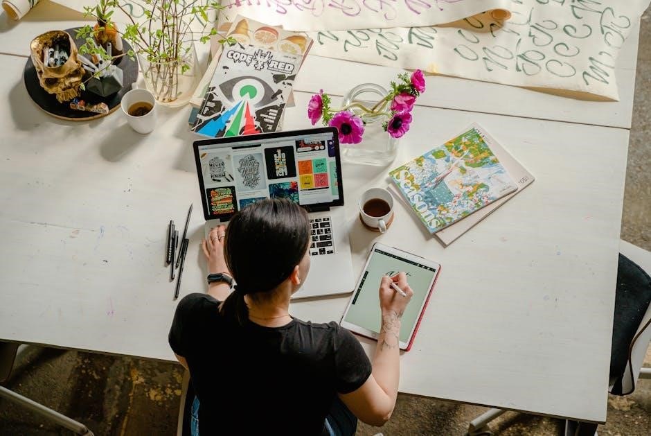
Using Digital Design for Print Matrices

Digital tools revolutionize the creation of printing matrices for manual printing techniques. Artists now utilize software to design intricate patterns and imagery, offering precision previously unattainable through purely manual methods.

This digital workflow allows for easy modification and experimentation with designs before committing to the physical matrix. Complex geometric shapes, detailed illustrations, and photographic elements can be seamlessly integrated into the artwork.

Once finalized, these digital designs are then transferred onto the chosen matrix – be it a woodblock, linoleum sheet, or lithographic stone – using various methods like laser etching, inkjet printing onto transfer paper, or direct drawing based on the digital template.

The integration of digital design expands creative possibilities, enabling artists to achieve greater complexity and control in their manual printing endeavors.

Scanning and Manipulating Manual Prints

Scanning manual prints opens a realm of possibilities for digital integration and artistic manipulation. High-resolution scans capture the nuances of texture, ink distribution, and subtle imperfections inherent in hand-printed artwork.

These digital images can then be imported into image editing software, allowing artists to adjust colors, contrast, and levels, enhancing specific details or creating unique visual effects. Layers can be added, combining multiple prints or incorporating digital elements.

Furthermore, scanned prints can be digitally collaged, resized, and repeated to create larger compositions or patterns. This process bridges the gap between traditional manual techniques and contemporary digital art practices.

The ability to manipulate scanned prints digitally allows for experimentation and refinement, extending the life and versatility of each original manual print.

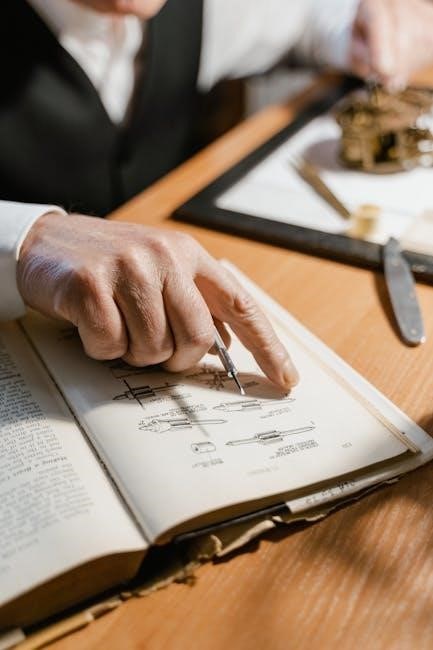
Resources and Further Learning

Online tutorials and guides, alongside workshops and classes, provide invaluable instruction in manual printing techniques, fostering skill development and artistic growth.

YouTube channels showcase demonstrations, while dedicated courses offer hands-on experience with various printing methods.

Online Tutorials and Guides

Numerous online resources cater to aspiring manual printers, offering a wealth of knowledge and practical demonstrations. Platforms like YouTube host channels dedicated to various printing techniques, such as relief printing, letterpress, and monoprinting. These videos often provide step-by-step instructions, showcasing the entire process from preparing the matrix to achieving a final, impressive print.

Beyond video tutorials, many websites and blogs offer detailed guides and articles covering specific techniques, materials, and troubleshooting tips. These resources often include photographic documentation and downloadable templates, aiding in the learning process. Searching for terms like “hand printing tutorial” or “relief printing guide” will yield a diverse range of options, suitable for beginners and experienced artists alike. Exploring these digital avenues provides accessible and affordable learning opportunities for anyone interested in the art of manual printing.

Workshops and Classes

Immersive learning experiences are readily available through manual printing workshops and classes offered by art centers, universities, and independent artists. These hands-on sessions provide invaluable guidance from experienced instructors, allowing participants to directly engage with the tools and techniques. Workshops often focus on specific methods, such as letterpress or wood engraving, offering in-depth exploration of the process.

Classes typically cover a broader range of printing techniques, providing a foundational understanding of the art form. The benefit of in-person instruction lies in the immediate feedback and personalized assistance, accelerating skill development. Searching online for “printmaking workshops near me” or checking local art school listings can reveal available opportunities. These experiences foster a collaborative learning environment and provide access to specialized equipment often unavailable for individual use.

overhead door legacy 850 owners manual

Overhead Door Legacy 850 Owners Manual: A Comprehensive Guide

This manual details operation and maintenance for the Legacy 850, compatible with residential doors up to 8ft, weighing 500lbs, featuring CodeDodger remotes.

Welcome to the Overhead Door Legacy 850 garage door opener! This robust system, designed for residential sectional doors, offers reliable performance and advanced features. The Legacy 850 is suitable for doors up to 8 feet in height and weighing up to 500 pounds, exceeding standard lifting force specifications for ½ horsepower openers.

This manual provides comprehensive guidance on installation, operation, maintenance, and troubleshooting. Key features include compatibility with Homelink and Car2U systems, alongside the secure CodeDodger remote control. Crucially, the Safe-T-Beam system must be installed for safe operation. This guide ensures you maximize the benefits of your Legacy 850.

Key Features and Specifications

The Overhead Door Legacy 850 boasts several key features. It’s designed for residential sectional doors, supporting heights up to 8 feet and weights up to 500 pounds. The ½ horsepower motor delivers substantial lifting force, exceeding Overhead Door’s specifications. CodeDodger remote technology provides enhanced security, and seamless integration exists with Homelink and Car2U systems for convenient control.

A vital safety component is the Safe-T-Beam system, required for operation. Installation is straightforward, and the opener is available with either belt or chain drive options. This manual details all specifications, ensuring optimal performance and longevity of your Legacy 850.

Safety Precautions

Prioritize safety during installation and operation of the Legacy 850. Always disconnect power before performing any maintenance or adjustments. The Safe-T-Beam system is crucial; ensure proper installation and regular testing to prevent door closure on obstructions. Never allow children to operate the opener or play near the door.

Inspect the door and opener monthly for proper balance and any signs of damage. Do not attempt repairs beyond your expertise; contact qualified service personnel. Failure to adhere to these precautions could result in serious injury or property damage. Refer to the full manual for comprehensive safety guidelines.

Installation Guide

Proper installation is vital for safe and reliable operation. This guide covers preparing the area, mounting the unit, connecting the door, and adjusting limits.

Preparing for Installation

Before beginning, ensure the garage door is balanced and operates smoothly. Disconnect the existing opener, if present, and verify all hardware is present within the Legacy 850 packaging. Clear the installation area of obstructions, providing ample workspace. Confirm the door’s weight and height fall within the specified limits – up to 8ft high and 500lbs.

Gather necessary tools: ladder, wrenches, screwdrivers, and a drill. The Safe-T-Beam system must be installed during this phase for operational safety. Review all included diagrams and safety precautions before proceeding. Proper preparation minimizes installation time and ensures a secure, functional system. Double-check power supply compatibility.

Mounting the Opener Unit

Securely attach the mounting brackets to the header above the garage door, ensuring they are level and firmly fastened to structural supports. Utilize appropriate hardware for your header type – wood or metal. Carefully position the Legacy 850 opener unit onto the mounted brackets, aligning the rail sections for smooth assembly.

Connect the rail sections, verifying proper alignment and secure fastening. Double-check all bolts and nuts are tightened to the manufacturer’s specifications. Ensure sufficient clearance around the unit for safe operation and future maintenance. This step is crucial for stable and quiet operation of the garage door system.

Connecting the Door

Attach the door bracket to the top section of your garage door, centering it for balanced operation. Connect the door arm to both the door bracket and the opener’s carriage, ensuring a secure connection using the provided hardware. Verify the door moves freely through its full range of motion without obstruction.

Adjust the arm’s length if necessary to achieve proper alignment and efficient power transfer. Improper connection can lead to uneven lifting or strain on the opener. Regularly inspect the connection points for wear and tear, tightening hardware as needed for continued safe and reliable performance.

Adjusting Travel Limits

Precisely set the up and down travel limits using the adjustment screws on the opener unit; Begin by loosening the locking nuts before making adjustments. Slowly rotate the screws to define the desired open and close positions, ensuring the door doesn’t overtravel or stop short of its intended limits.

Test the settings thoroughly after each adjustment, observing the door’s movement carefully. Retighten the locking nuts once the limits are accurately set to prevent accidental changes. Proper travel limit adjustment is crucial for safe operation and prevents potential damage to the door or opener.

Operation and Programming

The Legacy 850 utilizes the CodeDodger remote and is compatible with Homelink/Car2U systems; reprogramming is straightforward, and Safe-T-Beam adjustments are key.

Using the CodeDodger Remote

The CodeDodger remote provides secure access to your garage door, utilizing rolling code technology to prevent unauthorized entry. This system continually changes the access code after each use, enhancing security significantly. Programming additional remotes is a simple process, detailed within this manual, allowing for multiple users. Ensure the remote battery is functioning correctly for optimal performance. Refer to the section on battery replacement for instructions. The remote’s range can be affected by obstructions; maintain a clear line of sight for reliable operation. Learn how to program a new remote via online video tutorials for a visual guide.

Homelink and Car2U Compatibility

The Overhead Door Legacy 850 is designed for seamless integration with both Homelink and Car2U systems found in many vehicles. This compatibility allows you to control your garage door directly from your car’s dashboard, offering convenience and enhanced security. Programming typically involves a simple learning process, where the system recognizes the remote’s signal. Consult your vehicle’s owner’s manual for specific instructions on programming Homelink or Car2U. Ensure the remote is functioning correctly before attempting to link it. Troubleshooting guides are available online if you encounter any difficulties during the setup process.

Reprogramming the Garage Door Code

Reprogramming the Legacy 850’s garage door code is a crucial security measure, especially if you’ve lost a remote or suspect unauthorized access. The process involves accessing the learning mode on the opener unit, typically by pressing and holding a designated “Learn” button. Then, activate the remote you wish to program. The opener will recognize and store the new code. Online video tutorials demonstrate this process visually, simplifying the steps. Always clear all existing codes before programming new ones for maximum security; Refer to the full owner’s manual for detailed instructions and safety precautions.

Adjusting the Safe-T-Beam System

The Safe-T-Beam system is a vital safety feature of the Legacy 850, preventing the door from closing on obstructions. Proper adjustment ensures reliable operation. Begin by verifying the beams are aligned, indicated by steady lights on the opener unit. If the lights flash or are off, readjust the beam sensors until alignment is achieved. Regularly test the system by placing an object in the door’s path; the door should reverse immediately. Consult the owner’s manual for detailed troubleshooting steps if issues persist, ensuring the system functions correctly for enhanced safety.

Maintenance and Troubleshooting

Routine checks, belt/chain tension adjustments, and addressing common issues are crucial for the Legacy 850’s longevity; refer to the manual for guidance.

Routine Maintenance Schedule

To ensure optimal performance and longevity of your Overhead Door Legacy 850, a consistent maintenance schedule is highly recommended. Regularly inspect the door’s tracks for obstructions and ensure they remain clean and free of debris. Lubricate the moving parts, including rollers, hinges, and the chain or belt drive system, every six months with a silicone-based lubricant.

Visually examine the Safe-T-Beam system monthly to confirm proper alignment and functionality. Test the system by interrupting the beam while the door is closing. A full operational check, including remote control functionality and travel limit adjustments, should be performed annually. Following this schedule will help prevent potential issues and maintain the safety and reliability of your garage door opener.

Belt/Chain Tension Adjustment

Maintaining proper tension in the Legacy 850’s belt or chain drive is crucial for smooth, quiet operation and preventing premature wear. Regularly inspect the drive for excessive slack or tightness. If the chain appears loose, utilize the adjustment bolts located near the motor unit to incrementally tighten it, ensuring it doesn’t become overly strained.

For belt drives, check for signs of stretching or damage. Proper tension allows for efficient power transfer and reduces noise. Avoid over-tightening, as this can damage the motor or drive components. Consult a qualified technician if you are unsure about performing this adjustment, prioritizing safety and optimal performance.

Troubleshooting Common Issues

If your Legacy 850 isn’t responding, first check the power supply and ensure the Safe-T-Beam system is properly aligned and free from obstructions – it must be functional for the door to close. A non-working remote can often be resolved by replacing the battery or reprogramming it. For doors that reverse unexpectedly, verify the Safe-T-Beam and adjust force settings cautiously.

Noisy operation might indicate a need for belt/chain tension adjustment or lubrication. If issues persist, consult the full owner’s manual or contact Overhead Door customer support for assistance, avoiding potentially dangerous self-repairs.

Replacing the Remote Battery

To replace the battery in your CodeDodger remote for the Legacy 850, carefully open the remote’s casing, typically by sliding or prying it open – consult the manual for specifics. Remove the old battery, noting its polarity (+/-), and insert a fresh battery of the correct type. Ensure proper alignment before closing the casing securely.

A weak battery is a common cause of remote malfunction. After replacement, test the remote’s functionality. If problems continue, attempt reprogramming the remote to the garage door opener, following the instructions in the programming section of this manual.

Understanding the Safe-T-Beam System

The Safe-T-Beam system is crucial for safety; it must be installed for the Legacy 850 to close, preventing door descent upon obstruction detection.

Safe-T-Beam Installation Guidelines

Proper Safe-T-Beam installation is paramount for operational safety with your Overhead Door Legacy 850. Ensure the beam is positioned directly across the door opening, no higher than six inches above the floor. Mount the sensors securely, aligning them so the LED indicators face each other; Wiring must be carefully routed, avoiding any contact with moving door parts or sharp edges.

Confirm the beam’s path is unobstructed; even small items can interfere with functionality. Regularly inspect mounting brackets for tightness and alignment. The system requires power to operate, so verify connections are secure. Remember, the door will not close unless the Safe-T-Beam is correctly installed and functioning, safeguarding against potential hazards.

Testing the Safe-T-Beam Functionality

Thoroughly test the Safe-T-Beam system after installation and routinely thereafter for your Legacy 850. With the door closing, obstruct the beam’s path with a cardboard box. The door should immediately reverse to the open position, confirming the sensors are working correctly. Repeat this test several times, varying the obstruction’s location within the beam’s range.

Observe the LED indicators on the sensors; a solid light typically indicates proper alignment and function. If the door fails to reverse, re-check the installation, wiring, and alignment. A flashing light may signal an issue requiring troubleshooting. Prioritize this testing – it’s crucial for preventing accidents and ensuring safe operation.

Troubleshooting Safe-T-Beam Problems

If your Legacy 850’s Safe-T-Beam isn’t functioning, begin by verifying the power supply and wiring connections. Ensure the sensors are securely mounted and properly aligned – even slight misalignments can cause issues. Check the LED indicators; flashing lights often signal a problem. Clean the lens of each sensor with a soft cloth, removing any dirt or obstructions.

If problems persist, consult the owner’s manual for specific error codes. A disconnected wire or a faulty sensor may require replacement. Remember, the Safe-T-Beam is a critical safety feature; if you’re unable to resolve the issue, contact a qualified technician.

Technical Specifications

The Legacy 850 boasts a 1/2 HP motor, handling doors up to 8ft high and 500lbs. Standard 120V power is required for operation;

Motor Specifications (1/2 HP)

The Overhead Door Legacy 850 utilizes a robust ½ horsepower (HP) motor designed to provide reliable and efficient operation for residential garage doors. This motor is specifically engineered to handle the demands of frequent use while maintaining optimal performance. It’s capable of lifting and lowering doors with varying weights and sizes, adhering to Overhead Door’s stringent lifting force specifications.

The motor’s construction prioritizes durability and longevity, ensuring years of dependable service. It’s designed to work seamlessly with both belt and chain drive systems offered with the Legacy 850. Proper maintenance, as outlined in this manual, is crucial for maximizing the motor’s lifespan and preventing potential issues.

Door Weight and Height Limitations

The Overhead Door Legacy 850 opener is designed for standard residential sectional garage doors, with specific weight and height limitations to ensure safe and reliable operation. This model effectively manages doors up to a maximum height of 8 feet. Exceeding this height may compromise the opener’s performance and void the warranty.

Furthermore, the Legacy 850 is rated to handle doors weighing up to 500 pounds. Attempting to operate a door exceeding this weight limit can cause significant damage to the opener and potentially create a safety hazard. Always verify your door’s weight before installation and adhere to these specified limits.

Power Requirements

The Overhead Door Legacy 850 garage door opener operates on a standard 120-volt, 60Hz electrical supply, commonly found in most North American residences. A dedicated 15-amp circuit is recommended to prevent interference from other appliances and ensure optimal performance. It’s crucial to verify your electrical system meets these requirements before installation.

The opener utilizes a 1/2 horsepower motor, demanding sufficient power for smooth and efficient door operation. Proper grounding is essential for safety, protecting against electrical shock. Always consult a qualified electrician if you are unsure about your home’s electrical compatibility or installation procedures.

Warranty Information

The Legacy 850 includes a limited, non-transferable warranty; details are found within the owner’s manual. Contact customer support for specific claim procedures.

Limited Warranty Details

The Overhead Door Legacy 850 garage door opener is backed by a limited warranty, providing peace of mind to homeowners. This warranty covers defects in materials and workmanship under normal use for a specified period. The duration varies depending on the component – motor, parts, and functional components each have distinct coverage timelines.

It’s crucial to retain proof of purchase for warranty validation. The warranty is void if the opener is misused, improperly installed, or subjected to unauthorized modifications. Regular maintenance, as outlined in this manual, is essential to maintain warranty validity. This warranty does not cover labor costs associated with repairs or replacements.

Non-Transferable Warranty Clause

Please note that the Limited Warranty offered with the Overhead Door Legacy 850 garage door opener is strictly non-transferable. This means the warranty benefits are exclusively available to the original purchaser of the unit and cannot be passed on to subsequent owners of the property or the garage door opener itself.

Any attempt to transfer the warranty is considered a breach of the warranty agreement and will immediately void all coverage. This clause ensures that the warranty remains a direct benefit to the initial buyer, incentivizing proper maintenance and responsible use throughout the product’s lifespan. Proof of original purchase is required for all warranty claims.

Contacting Customer Support

For assistance with your Overhead Door Legacy 850, or to address any questions regarding installation, operation, or warranty claims, our dedicated customer support team is readily available. We strive to provide prompt and helpful service to ensure your complete satisfaction. Please have your model number and date of purchase available when contacting us.

You can reach us via phone during business hours, or through our online support portal, which features a comprehensive FAQ section and troubleshooting guides. Detailed contact information, including phone numbers and email addresses, can be found within this owner’s manual and on our official website.

Remote Control Programming

Programming remotes for the Legacy 850 is straightforward, utilizing the CodeDodger system. Additional remotes can be added, and existing codes cleared easily.

Programming Additional Remotes

To program additional CodeDodger remotes for your Overhead Door Legacy 850, begin by ensuring the garage door opener is compatible with the remote you intend to use. Locate the “Learn” button on the opener unit – it’s typically yellow or orange. Press and release this button; a small indicator light will illuminate. Within thirty seconds, press and hold the button on the new remote you wish to program.

The indicator light on the opener unit should blink or change color, confirming successful programming; Release the button on the remote. Test the remote by pressing it to operate the garage door. Repeat this process for each additional remote you want to add to the system. If programming fails, consult the full owner’s manual for detailed troubleshooting steps.

Clearing All Remote Codes

If you need to erase all programmed remote codes on your Overhead Door Legacy 850, locate the “Learn” button on the garage door opener unit. This button is crucial for resetting the system’s memory. Press and hold the “Learn” button continuously until the indicator light begins to flash rapidly. This flashing sequence signifies that all previously programmed remote codes have been successfully cleared from the system’s memory.

After the light stops flashing, release the button. Now, you will need to reprogram all your remotes. This process ensures only authorized users have access to operate your garage door, enhancing security. Refer to the “Programming Additional Remotes” section for detailed instructions.

CodeDodger Remote Features

The CodeDodger remote, included with your Overhead Door Legacy 850, offers enhanced security through rolling code technology. This means each time the remote is used, a new code is generated, preventing unauthorized access even if the code is intercepted. The remote is designed for simple, user-friendly operation, allowing for convenient control of your garage door.

It’s compatible with Homelink and Car2U systems for seamless integration with your vehicle. The remote’s compact design makes it easy to carry, and its durable construction ensures long-lasting performance. Explore the programming options to personalize your experience.

Advanced Settings and Adjustments

Fine-tune your Legacy 850 with force, speed, and vacation mode controls for optimal performance and security, customizing operation to your specific needs.

Force Adjustment Settings

The Legacy 850’s force adjustments are critical for safe and reliable operation. These settings dictate the amount of power the opener applies to overcome door weight and resistance. Improper adjustment can lead to operational issues or, more importantly, safety hazards. Carefully follow the manufacturer’s guidelines when modifying these settings.

Adjustments should only be made if the door struggles to fully open or close, or if the Safe-T-Beam system is frequently triggered. Start with small increments and thoroughly test the door’s operation after each adjustment. Excessive force can damage the door or opener, while insufficient force may result in the door reversing unexpectedly. Always prioritize safety and consult a qualified technician if you are unsure about any aspect of the force adjustment process.

Up/Down Speed Control

The Overhead Door Legacy 850 allows for adjustable up and down speeds, influencing the door’s overall operation. Modifying these settings impacts both convenience and safety. Faster speeds offer quicker access, but may increase stress on the door and opener components. Slower speeds provide smoother, quieter operation, and enhance safety, particularly around children and pets.

Adjustments are typically made via dip switches or electronic settings within the opener unit. Refer to the detailed instructions in this manual for specific procedures. Always test the door’s full range of motion after any speed adjustment. Ensure the Safe-T-Beam system functions correctly at all speeds. Prioritize safety and avoid excessively high speeds.

Vacation Mode Activation

The Legacy 850’s Vacation Mode enhances security during extended absences. When activated, the opener disables remote controls and the wall button, preventing unauthorized access. The door can still be operated manually from the inside, ensuring emergency egress. This feature is crucial for deterring potential intruders while you’re away.

Activation typically involves a specific button sequence on the opener unit or through the CodeDodger remote. Consult the detailed instructions within this manual for precise steps. Remember to deactivate Vacation Mode upon your return to restore normal operation. Always verify the mode’s status before relying on remote access.

clicker keypad instruction manual

Clicker universal garage door opener wireless keyless entry systems, like model KLIK2U, offer convenient access. Understanding the instructions is crucial for successful operation.

These systems eliminate the need for physical remotes, providing secure and straightforward control of your garage door. Proper setup ensures reliable performance.

This guide will walk you through the process, covering everything from initial preparation to advanced features, referencing the Clicker keypad manual.

What is a Clicker Keypad?

A Clicker keypad is a wireless keyless entry system designed for garage door operation, offering a convenient alternative to traditional remote controls. Models like KLIK2U allow access using a personal four-digit code, eliminating the need to carry or search for a remote.

This device mounts near your garage door and communicates wirelessly with your garage door opener. It’s a particularly useful solution for households with multiple users, or for those who frequently misplace remotes. The Clicker system provides a secure and reliable method of controlling access to your home.

Referencing the instruction manual is vital for understanding its features and ensuring proper installation and programming. It’s a universal system, compatible with many brands, but some, like Genie’s rotating code systems, present incompatibility issues.

Benefits of Using a Clicker Keypad

Employing a Clicker keypad, as detailed in the instruction manual, delivers numerous advantages. Foremost is the elimination of lost or misplaced garage door remotes, enhancing security and convenience. The keyless entry system allows multiple users to have unique codes, providing controlled access.

Installation is generally straightforward, and the Clicker is compatible with a wide range of garage door opener brands – Chamberlain, Sears, and others – though incompatibility exists with some Genie systems. The model KLIK2U offers a reliable and secure alternative.

Furthermore, a keypad reduces the risk of unauthorized access compared to readily duplicated remotes. Following the programming instructions carefully ensures optimal performance and peace of mind for homeowners.

Understanding Your Clicker Model

Identifying your specific Clicker model (KLIK2U, CLK1D) is the first step, as instructions vary. Refer to your manual for detailed compatibility information.

Identifying Your Specific Clicker Model (e.g., KLIK2U, CLK1D)

Clicker keypads come in various models, with KLIK2U and CLK1D being common examples. Locating the exact model number is vital for accessing the correct programming instructions and troubleshooting guidance. This number is typically found on a sticker located on the back of the keypad unit itself, or within the battery compartment.

The Clicker keypad manual specific to your model provides detailed diagrams and step-by-step procedures. Downloading the official manual (CLK1D, CLK1D2) from the manufacturer’s website ensures you have the most accurate and up-to-date information. Knowing your model also helps determine compatibility with your garage door opener, avoiding potential issues during setup.

Incorrect instructions used for the wrong model can lead to programming failures or malfunction. Always double-check the model number before proceeding with any programming steps.

Compatibility with Garage Door Openers

Clicker keypads are designed for universal compatibility, but certain limitations exist. The Clicker is generally compatible with most garage door openers, including those from Chamberlain and Sears, as outlined in the instruction guides. However, it’s crucial to note a significant incompatibility: Genie garage door openers utilizing rotating code systems.

These rotating code systems employ a different security protocol, preventing seamless integration with standard Clicker keypads. Before purchasing or programming, verify your garage door opener’s brand and security features. Referencing the Clicker keypad manual will detail specific compatibility information.

Proceeding with instructions on incompatible systems may result in failure; Always confirm compatibility to ensure a successful and secure setup.

Incompatibility Issues (e.g., Genie rotating code systems)

A primary concern when using a Clicker keypad is incompatibility with certain garage door opener systems, notably Genie’s rotating code technology. These systems generate a new security code each time the opener is used, a feature the standard Clicker cannot interpret. Attempting to program a Clicker with a Genie rotating code opener will likely result in failure, as detailed in the instruction manual.

The Clicker keypad manual explicitly states this limitation. Users with Genie openers should explore alternative keyless entry solutions specifically designed for rotating code compatibility. Ignoring this incompatibility can lead to frustration and a non-functional system. Always verify your opener’s type before proceeding with programming.

Initial Setup and Preparation

Before programming your KLIK2U Keyless Entry, gather required tools and information. Review the Clicker keypad manual and prioritize safety precautions for a smooth process.

Required Tools and Information

To successfully program your Clicker keypad, specifically models like KLIK2U or CLK1D, you’ll need a few essential items. First, have your existing garage door opener remote control readily available – this is crucial for transferring the code.

Ensure you have access to a working power source for the keypad itself, as it requires battery power to function during the programming sequence.

Most importantly, locate and carefully read the Clicker keypad manual (CLK1D, CLK1D2) for detailed, model-specific instructions. Knowing your garage door opener’s brand (Chamberlain, Sears, etc.) is also vital, as compatibility varies.

Finally, a clear, well-lit workspace will make the process easier and more efficient.

Safety Precautions Before Programming

Prior to programming your Clicker keypad, prioritizing safety is paramount. NEVER permit anyone to cross the path of a moving gate or door during testing or operation. Ensure the area around the garage door is clear of people and obstructions.

Always supervise the programming process and be prepared to immediately stop the door’s operation if any unexpected behavior occurs.

Review the Clicker keypad manual thoroughly, paying close attention to any warnings or cautions. Understand that the Clicker isn’t compatible with all systems, like Genie’s rotating code, potentially causing malfunctions.

If unsure about any step, consult a qualified technician before proceeding.

Programming the Clicker Keypad

Programming involves using an existing remote or directly entering a new code on the CLICKER keypad. Watch for the purple flash LED indicator during the process.

Programming with Existing Garage Door Opener Remote

To program your Clicker keypad using an existing garage door opener remote, begin by ensuring the keypad is in programming mode. Press the “Learn” button on your garage door opener motor unit – its location varies by brand, so consult your opener’s manual if needed.

Within 30 seconds, press and release the button on your garage door opener remote that you wish to program to the Clicker keypad. Both LEDs on the keypad will flash purple, signaling successful receipt of the remote’s signal.

If the LEDs do not flash purple, repeat the process, ensuring you are within range and that the remote has a fresh battery. This method effectively links your existing remote’s code to the keypad for convenient access.

Entering a New Code on the Keypad

If you need to establish a new, unique code on your Clicker keypad, begin by pressing the “Program” button. The keypad’s LED will illuminate, indicating it’s ready for code input. Carefully enter a four-digit code using the numeric buttons. Avoid easily guessable combinations for enhanced security.

After entering your desired code, press the “Program” button again to confirm. The keypad will briefly display the entered code, then the LEDs will flash purple, signifying successful code registration.

Test the new code immediately to ensure functionality. Remember to keep your code confidential and consider changing it periodically for optimal security.

LED Indicator Signals During Programming (Purple Flash)

The Clicker keypad utilizes LED signals to communicate programming status. A consistent purple flash is a key indicator of successful communication between the keypad and your garage door opener. This flash confirms the keypad is learning or has successfully stored a new code.

If the LED flashes rapidly in purple, it suggests a potential issue with the signal or compatibility. A solid purple light typically means the keypad is in programming mode, awaiting input.

Pay close attention to these signals during the programming process; they provide valuable feedback. Refer to the Clicker manual for a complete understanding of all LED indicators.

Troubleshooting Common Issues

If your Clicker keypad isn’t responding, or the code isn’t working, check compatibility with brands like Chamberlain and Sears. Consult the manual!

Keypad Not Responding

If the Clicker keypad fails to respond, begin by verifying the battery’s charge. A weak battery is a frequent cause of operational issues. Ensure the battery is correctly installed, observing the proper polarity as indicated inside the battery compartment.

Next, confirm that the keypad is within range of your garage door opener’s receiver. Excessive distance or obstructions can interfere with the signal. Try operating the keypad closer to the garage door opener unit.

Review the programming steps outlined in the Clicker keypad manual to ensure the keypad is correctly paired with your garage door opener. A failed or incomplete programming sequence will prevent functionality. Finally, check for any potential interference from other wireless devices.

Code Not Working

If your programmed code isn’t working, double-check the entered digits against your original code. Even a single incorrect number will prevent access. Refer to the Clicker keypad manual for the correct programming procedure and ensure each step is followed precisely.

Consider that some garage door openers, particularly Genie models utilizing rotating code systems, are incompatible with Clicker keypads. Verify compatibility before proceeding with programming. If compatibility isn’t an issue, attempt to reprogram the keypad following the manual’s instructions.

Ensure no recent changes have been made to your garage door opener’s settings, as this could invalidate the programmed code. A factory reset of the opener might be necessary in some cases.

Compatibility Problems with Specific Brands (Chamberlain, Sears)

While the Clicker keypad boasts broad compatibility, issues can arise with certain brands like Chamberlain and Sears. The Clicker manual notes that programming procedures may vary depending on the specific model of your garage door opener. Always consult your opener’s documentation alongside the Clicker instructions.

For Chamberlain and Sears openers, ensure you’re following the correct “TYPE 4” programming sequence as outlined in the Clicker instructions. Incorrectly selecting the type will prevent successful code entry. If problems persist, check for firmware updates on your garage door opener.

Some older Chamberlain and Sears models may require a compatibility bridge or adapter for seamless integration with the Clicker keypad.

Advanced Features and Settings

The Clicker keypad allows backlight adjustment for visibility and easy battery changes to maintain functionality. Refer to your manual for detailed instructions.

Adjusting Keypad Backlight

Clicker keypad backlighting enhances visibility in low-light conditions, making operation easier and safer. While specific instructions may vary slightly depending on your model (like CLK1D or CLK1D2), the general process is straightforward. Typically, adjusting the backlight involves a dedicated button or a sequence of key presses on the keypad itself.

Consult your Clicker manual for the precise method applicable to your device. Some models offer multiple brightness levels, allowing you to customize the illumination to your preference. Experiment with the settings to find the optimal balance between visibility and battery conservation. A brighter backlight consumes more power, potentially reducing battery life. Remember to always refer to the official instructions for the most accurate guidance.

Changing the Battery

Maintaining your Clicker keypad requires periodic battery replacement. A low battery can cause operational issues, such as unresponsive buttons or a diminished signal range. The Clicker manual details the specific battery type required for your model – typically a 9V battery. Before replacing the battery, ensure you have a compatible replacement readily available.

Carefully open the battery compartment, usually located on the back of the keypad unit. Remove the old battery and connect the new one, observing the correct polarity (+ and -). Securely close the battery compartment. After replacement, you may need to reprogram the keypad to your garage door opener; refer to the programming instructions.

Clicker Keypad Manual Resources

Download the official Clicker manual (CLK1D, CLK1D2) online for detailed instructions. Find FAQs and support to resolve any programming or operational issues;

Downloading the Official Manual (CLK1D, CLK1D2)

Clicker Model CLK1D and CLK1D2 owners can easily access comprehensive documentation online. Obtaining the official manual provides detailed instructions for programming, troubleshooting, and understanding all features.

These manuals are typically available as PDF files, ensuring compatibility across various devices. A quick online search for “Clicker CLK1D manual” or “Clicker CLK1D2 manual” will lead you to the official download locations.

The manual covers essential topics like initial setup, entering new codes, interpreting LED indicator signals (like the purple flash during programming), and addressing common compatibility concerns. It’s a valuable resource for maximizing your keyless entry system’s functionality.

Always refer to the official documentation for the most accurate and up-to-date information regarding your specific Clicker keypad model.

Finding Online Support and FAQs

Beyond the official Clicker keypad manual, numerous online resources offer support and answers to frequently asked questions. Many websites host dedicated FAQ sections addressing common programming issues and compatibility concerns with brands like Chamberlain and Sears.

Online forums and communities dedicated to home automation often feature discussions about Clicker systems, providing a platform to share experiences and solutions. Searching for specific error messages or problems can quickly yield helpful insights.

Manufacturer support websites often provide troubleshooting guides and contact information for direct assistance. Remember that the Clicker is not compatible with some Genie rotating code systems, so check compatibility first.

Utilizing these resources can streamline the setup process and resolve issues efficiently, ensuring a smooth experience with your keyless entry system.

kenmore model 417 washer dryer combo repair manual

Kenmore Model 417 Washer Dryer Combo Repair Manual: A Comprehensive Guide

This manual provides detailed instructions for repairing your Kenmore 417 washer/dryer combo, offering diagrams, parts lists, and troubleshooting guidance for effective repair projects;

Understanding the Kenmore 417 Combo Unit

The Kenmore 417 is a versatile all-in-one washer and dryer, designed for convenience in smaller living spaces․ This unit combines washing and drying cycles within a single appliance, eliminating the need for separate machines․ Understanding its integrated functionality is crucial for effective repair․

Commonly, the Kenmore 417 features a variety of wash cycles, temperature settings, and drying options․ It utilizes a single drum for both processes, employing a ventless drying system to conserve energy and simplify installation․ The control panel allows users to select desired settings, and error codes are displayed to indicate potential issues․

Before attempting any repair, familiarize yourself with the unit’s basic components, including the water inlet valve, drain pump, heating element, drive belt, and door latch․ Knowing how these parts interact will streamline the troubleshooting and repair process․

Locating the Repair Manual & Model Information

Finding the correct repair manual for your Kenmore 417 Washer Dryer Combo is the first step towards successful troubleshooting․ Sears Parts Direct is a valuable resource, offering downloadable manuals and part diagrams specifically for this model․ You can also often find Kenmore Service Manuals available in PDF format online․

Accurate model information is essential․ Locate the model number – often found on a sticker inside the door, on the back of the unit, or within the user manual․ Common model numbers include 417․61722510 and 417․90802991․ Having this number ensures you access the correct repair information and order compatible replacement parts․

Many appliance repair websites also offer free DIY manuals and troubleshooting guides․ Searching online using your specific model number will yield the most relevant results․

Safety Precautions Before Repair

Prioritize safety before attempting any repair on your Kenmore 417 Washer Dryer Combo․ Disconnect the appliance from the power outlet – this is crucial to prevent electrical shock․ Turn off both the water supply valves to prevent flooding during washer component repair․

Wear appropriate safety gear, including gloves and eye protection․ Be mindful of sharp edges inside the appliance․ If you are unfamiliar with electrical work, consult a qualified technician․ Improper repair can lead to injury or further damage․

Never work on a wet surface․ Ensure the area around the appliance is dry and well-lit․ Always double-check that the power is off before touching any internal components․ Following these precautions will help ensure a safe repair process․

Common Problems & Troubleshooting

Kenmore 417 combo units can experience several common issues․ A washer not starting often points to a faulty door latch – ensure it’s securely closed․ A dryer failing to heat usually indicates a problem with the heating element or thermal fuse․ Excessive vibration during the wash cycle can stem from an unbalanced load or worn shock absorbers․

Water leaks frequently occur due to damaged hoses or a faulty water inlet valve․ Before assuming major issues, check for simple causes like overloaded drums or clogged drain pumps․ Consult the error codes displayed (see section on Error Codes) for specific diagnostic clues․

Regularly inspecting these areas can prevent minor problems from escalating into costly repairs․

Washer Not Starting

If your Kenmore 417 washer isn’t starting, the most frequent culprit is a malfunctioning door latch․ Verify the door is completely closed and latched; a slightly ajar door prevents operation․ If the latch appears functional, test its continuity with a multimeter – a lack of continuity indicates a faulty latch requiring replacement․

Another potential cause is a blown thermal fuse, protecting the motor from overheating․ Check the fuse for continuity as well․ A faulty control board can also prevent the washer from initiating a cycle․ Inspect wiring connections for looseness or damage․ Finally, ensure the unit is receiving power and the outlet is functioning correctly․

Dryer Not Heating

When the Kenmore 417 dryer fails to heat, the heating element is often the primary suspect․ Use a multimeter to test the element for continuity; a break in the circuit signifies a need for replacement․ Before testing, ensure the unit is disconnected from power․ Another common issue is a faulty thermal fuse, designed to prevent overheating․ Check its continuity as well․

Inspect the gas valve (for gas models) or the control board for proper operation․ A malfunctioning gas valve won’t allow gas flow, while a faulty control board may not send power to the heating element․ Also, examine the thermal bi-metal stat, which regulates temperature; a defective stat can interrupt the heating cycle․

Excessive Vibration During Wash Cycle

Excessive vibration during the wash cycle of your Kenmore 417 often indicates an unbalanced load․ Redistribute the clothes evenly within the drum․ However, persistent shaking suggests mechanical issues․ First, check the suspension rods or springs; these absorb shock and maintain stability․ Worn or broken components need replacement․

Inspect the shock absorbers for leaks or damage, as they contribute to dampening vibrations․ A failing drive belt can also cause imbalance․ Ensure the washer is level on the floor; adjust the feet as needed․ Finally, verify the drum bearings aren’t worn, as this can lead to significant wobble and noise during operation․

Water Leaks During Operation

Water leaks in your Kenmore 417 can stem from several sources․ Begin by inspecting the water inlet hoses and drain hose connections for tightness and cracks․ Check the door boot (gasket) for tears or debris preventing a proper seal․ A damaged boot is a common leak point․

Examine the pump housing and drain pump for cracks or loose connections․ Internal leaks might indicate a failing water inlet valve or a damaged tub seal․ Inspect the tub itself for any visible cracks․ Carefully observe where the leak originates during a wash cycle to pinpoint the issue․ Addressing these areas promptly prevents further water damage and ensures efficient operation․

Essential Tools for Repair

Successfully repairing your Kenmore 417 requires a basic toolkit․ A Phillips head screwdriver is crucial for most disassembly tasks․ A flathead screwdriver assists with prying and accessing certain components․ Pliers, both standard and needle-nose, are essential for gripping and manipulating parts․

A socket wrench set with various sizes provides leverage for removing bolts and fasteners․ A multimeter is vital for testing electrical components like the heating element and continuity․ Don’t forget a rubber mallet for gently loosening stuck parts․ Safety glasses and work gloves are paramount for personal protection․ Having these tools readily available streamlines the repair process․

Replacing the Door Latch Assembly

A faulty door latch prevents the Kenmore 417 from starting․ Begin by disconnecting power․ Remove the top panel for access․ Locate the latch assembly, typically near the door frame․ Disconnect the wiring harness connected to the latch․ Unscrew the latch from the machine’s frame – usually two screws secure it․

Carefully pull the old latch assembly out․ Install the new latch, ensuring proper alignment․ Reconnect the wiring harness securely․ Replace the screws, tightening them firmly․ Test the new latch by manually closing the door and verifying it engages․ Restore power and run a test cycle to confirm proper operation․

Diagnosing and Replacing the Water Inlet Valve

Insufficient water entering the Kenmore 417 often indicates a faulty water inlet valve․ First, disconnect power․ Locate the valve – usually at the back of the machine where water hoses connect․ Check the screen filters within the valve inlets for debris; clean if necessary․

To test, use a multimeter to check for continuity across the valve’s solenoid terminals when energized․ No continuity means replacement is needed․ Disconnect the hoses and electrical connections․ Remove the old valve, noting hose and wire routing․ Install the new valve, reconnecting hoses and wires securely․ Restore power and test for proper water flow during a wash cycle․

Cleaning the Drain Pump Filter

A clogged drain pump filter is a common cause of drainage issues in the Kenmore 417․ Locate the filter – typically behind a small access panel at the front, lower part of the machine․ Before opening, place towels to absorb any residual water․

Carefully unscrew and remove the filter․ Inspect for obstructions like lint, coins, or small objects․ Thoroughly clean the filter under running water, removing all debris․ Reinstall the filter, ensuring it’s securely tightened to prevent leaks․ Run a short spin cycle to verify proper drainage․ Regular cleaning – every few months – prevents future blockages and maintains optimal performance․

Checking and Replacing the Drive Belt

A worn or broken drive belt can prevent the drum from spinning․ To access the belt, you’ll likely need to remove the back panel of the Kenmore 417․ Visually inspect the belt for cracks, fraying, or signs of wear․ If damaged, proceed with replacement․

Before removing the old belt, note its routing around the motor pulley and drum․ Carefully detach the old belt and install the new one, ensuring it’s properly seated in the grooves․ Reassemble the back panel․ Test the washer by running a cycle to confirm the drum spins correctly․ A properly functioning drive belt is crucial for the wash and spin cycles․

Testing the Heating Element (Dryer)

A faulty heating element is a common cause of the dryer not heating․ Before testing, disconnect power to the Kenmore 417․ Locate the heating element housing, typically at the rear of the dryer․ Disconnect the wires connected to the element․

Using a multimeter set to the ohms setting, test the element for continuity․ A reading of zero or a low resistance indicates a good element․ An infinite reading signifies a broken element requiring replacement․ If replacing, ensure the new element is identical to the old one․ Reconnect the wires and restore power, then test the dryer’s heating function․

Understanding Error Codes

The Kenmore 417 utilizes error codes to diagnose internal issues․ These codes, displayed on the control panel, pinpoint the source of the problem, simplifying repairs․ Common codes include F01, indicating a water level sensor malfunction, potentially requiring sensor replacement or wiring checks․ E02 signals a drain pump malfunction, often due to blockage or pump failure – inspect the drain hose and pump itself․

Refer to the complete error code list in the service manual for a comprehensive understanding․ Resetting the machine by disconnecting power for a few minutes can sometimes clear minor errors․ However, persistent codes necessitate further investigation and potential part replacement․

Error Code F01: Water Level Sensor Issue

Error code F01 on the Kenmore 417 indicates a problem with the water level sensor, preventing accurate water filling․ This can manifest as the washer failing to start, overfilling, or not filling at all․ Troubleshooting begins with inspecting the sensor’s wiring harness for loose connections or damage․ A faulty sensor itself is a common cause, requiring replacement․

To test the sensor, use a multimeter to check its resistance; consult the service manual for correct values․ Before replacing, ensure the water inlet valve isn’t obstructed․ If the wiring and sensor test normal, the main control board might be the issue, though this is less frequent․

Error Code E02: Drain Pump Malfunction

Error code E02 on your Kenmore 417 signals a malfunction within the drain pump system․ This typically means the washer isn’t effectively removing water after a wash cycle․ Initial checks should focus on the drain pump filter for obstructions like lint, coins, or small articles of clothing – a frequent cause․

If the filter is clear, test the drain pump itself for continuity using a multimeter․ A lack of continuity indicates a failed pump needing replacement․ Also, inspect the pump’s wiring and connections for damage․ A blocked drain hose can mimic this error, so verify its clear path to the drain․ Finally, a faulty control board could also trigger this code․

Sourcing Replacement Parts

Finding replacement parts for your Kenmore 417 washer dryer combo is crucial for successful repairs․ Sears Parts Direct is a primary resource, offering a comprehensive catalog specifically tailored to Kenmore appliances, including detailed parts diagrams for your model․ You can also explore appliance parts retailers online, comparing prices and availability․

When ordering, always verify the part number matches your Kenmore 417’s specific configuration․ Providing the complete model number (e․g;, 417․61722510) ensures accuracy․ Local appliance repair shops may also stock common parts or can order them for you․ Consider checking online marketplaces, but prioritize reputable sellers to guarantee part quality and authenticity․

Disassembly and Reassembly Guide

Disassembly requires careful documentation; photograph each step to aid reassembly․ Begin by disconnecting power and water supply․ Access internal components by removing the top and front panels, noting screw locations․ Gently disconnect wiring harnesses, labeling them for correct reconnection․ When removing parts like the drum or pump, observe their orientation and surrounding components․

Reassembly follows the reverse order․ Ensure all wiring is securely connected, referencing your photos․ Verify proper alignment of parts before tightening screws․ Double-check for any forgotten components or loose connections․ Before restoring power, inspect for any obstructions or potential hazards․ A methodical approach prevents damage and ensures optimal performance․

Preventative Maintenance Tips

Regular cleaning is crucial; wipe down the exterior and door seal after each use․ Monthly, clean the lint filter thoroughly to maintain dryer efficiency and prevent fire hazards․ Every six months, run a cleaning cycle with a washing machine cleaner to remove residue and odors․ Inspect the water inlet hoses for cracks or leaks, replacing them as needed․

Annually, check the drain pump filter for obstructions․ Avoid overloading the machine, as this strains components․ Level the unit to minimize vibration․ Proper ventilation is vital for the dryer; ensure the exhaust vent is clear․ Following these tips extends the lifespan of your Kenmore 417 and minimizes potential repairs․

Where to Find Additional Support & Resources

Sears Parts Direct offers a wealth of information, including manuals, parts diagrams, and replacement parts specifically for your Kenmore 417․ Online appliance repair forums and communities provide a platform to connect with experienced users and technicians for advice․ YouTube hosts numerous video tutorials demonstrating common repair procedures for similar models․

Kenmore’s official website may have downloadable service manuals and FAQs․ Consider contacting a qualified appliance repair technician for complex issues․ Websites specializing in appliance repair offer expert help and troubleshooting guides․ Remember to have your model number readily available when seeking assistance to ensure accurate information and parts compatibility․

Electrical Diagram Overview

The Kenmore 417’s electrical system integrates both washer and dryer circuits; Diagrams illustrate the power supply, motor controls, heating element circuitry, and sensor connections․ Understanding these diagrams is crucial for diagnosing electrical faults․ Key components include the main control board, timer, door interlock switches, and wiring harnesses․

Troubleshooting requires a multimeter to test continuity, voltage, and resistance․ Safety is paramount; always disconnect power before working on electrical components․ Diagrams detail the grounding system and safety features․ Identifying the correct wire colors and connector types is essential for accurate repair․ Refer to the service manual for detailed schematics and component locations․

light fixture insturctions manual

Light Fixture Installation Manual: A Comprehensive Guide

This manual details upgrading spaces with energy-efficient LED fixtures, modernizing room aesthetics, and providing essential installation steps for a safe and effective process.

Safety Precautions

Prioritize safety during light fixture installation! Always turn off the power at the breaker box before commencing any work. Verify the power is off using a non-contact voltage tester. Wear appropriate safety glasses to protect your eyes from falling debris.

Use a sturdy ladder and ensure it’s securely positioned. Never work with electricity in wet conditions. If unsure about any step, consult a qualified electrician. Incorrect wiring can lead to fire hazards or electrical shock. Follow all local electrical codes and regulations for a safe installation.

Essential Tools and Materials

Gathering the right tools is crucial for a smooth installation. You’ll need a screwdriver set (flathead and Phillips), wire strippers, wire nuts, electrical tape, a non-contact voltage tester, and pliers. A ladder is essential for reaching the fixture.

Materials include the new light fixture, mounting bracket (if needed), appropriate wire connectors, and potentially drywall anchors. Ensure the fixture is compatible with your existing junction box. Having these items prepared beforehand streamlines the process and enhances safety.

Understanding Light Fixture Types

Different fixtures require varied installation approaches. Flush mount fixtures sit directly against the ceiling, offering a low profile. Semi-flush mounts have a small gap, providing a bit more decorative space.

Chandeliers and pendants hang down, needing secure support and potentially longer wiring. Understanding the fixture type dictates the mounting bracket and wiring techniques. Consider the weight and size when selecting appropriate hardware for a safe and aesthetically pleasing result.

Flush Mount Fixtures

Flush mounts are ideal for lower ceilings, providing ample illumination without significant hanging space. These fixtures attach directly to the junction box, simplifying installation. Ensure the mounting bracket is securely fastened, supporting the fixture’s weight.

Wiring is straightforward, connecting the fixture wires to the house wiring using wire nuts and electrical tape. Confirm a snug fit and proper insulation before mounting the fixture flush against the ceiling, creating a clean, integrated look.

Semi-Flush Mount Fixtures

Semi-flush mounts offer a balance between flush mounts and chandeliers, featuring a short gap between the fixture and the ceiling. Installation involves a mounting bracket, similar to flush mounts, but allows for a decorative element to extend downwards.

Carefully align the fixture with the bracket, ensuring secure attachment. Wiring procedures remain consistent – connect wires with nuts and tape. These fixtures provide enhanced style while maintaining practicality for various room sizes and ceiling heights.

Chandeliers & Pendants

Chandeliers and pendants introduce dramatic flair, often requiring more robust ceiling support due to their weight. Installation necessitates a securely mounted bracket capable of handling the fixture’s mass.

Carefully follow the manufacturer’s instructions for assembly and attachment. Wiring connections are crucial; ensure proper grounding and secure wire nut connections. Adjust chain or cord length for desired height and aesthetic appeal, creating a focal point within the space.

Preparing for Installation

Prior to commencing any electrical work, meticulous preparation is paramount for safety and success. Begin by turning off the power to the circuit at the breaker box, verifying with a non-contact voltage tester.

Next, remove the old fixture carefully, noting the wiring configuration. Inspect the junction box for damage and ensure it’s securely mounted. Gather all necessary tools and materials, referencing the provided list, to streamline the installation process.

Turning Off the Power

Safety is the utmost priority; therefore, completely disconnecting the electrical supply is crucial before any work begins. Locate the circuit breaker controlling the light fixture and switch it to the “off” position.

Always double-check that the power is indeed off using a non-contact voltage tester at the fixture’s wires. Never assume the breaker is correctly labeled; verification is essential to prevent electrical shock and ensure a safe working environment.

Removing the Old Fixture

With the power safely disconnected, carefully remove the old light fixture. Begin by unscrewing any decorative elements or covers. Support the fixture’s weight as you disconnect the wiring, noting the wire connections for reference during the new fixture installation;

Gently lower the fixture and detach it from the mounting bracket. Inspect the junction box for any damage and address it before proceeding.

Installing the Mounting Bracket

Securely attaching a new mounting bracket is crucial for supporting the fixture’s weight. Ensure the bracket is compatible with your junction box and the new light fixture. Align the bracket holes with the box’s mounting points.

Use appropriate screws to firmly fasten the bracket, avoiding over-tightening. This bracket will hold the new light securely in place, providing a stable foundation for the installation process.

Securing the Bracket to the Junction Box

Properly securing the bracket to the junction box is paramount for safety and stability. Utilize screws specifically designed for electrical boxes, ensuring they penetrate the box’s structure firmly.

Avoid stripping the screw holes by applying consistent pressure while tightening. A wobbly bracket indicates insufficient support; re-evaluate and reinforce if necessary. This foundational step prevents future fixture movement and potential electrical hazards.

Wiring the New Light Fixture

Carefully connecting wires is crucial for a functional and safe installation. Begin by identifying the hot (usually black), neutral (white), and ground (green or bare copper) wires.

Twist wires together clockwise, secure with wire nuts, and wrap with electrical tape for insulation. Ensure a tight connection to prevent shorts or loose wiring. Double-check all connections before proceeding, prioritizing safety throughout the process.

Identifying Wires (Hot, Neutral, Ground)

Accurate wire identification is paramount for safe electrical work. The hot wire, typically black, carries the electrical current. The neutral wire, usually white, provides the return path. The ground wire, often green or bare copper, is a safety conductor.

Always verify with a non-contact voltage tester before handling any wires. Incorrect wiring can lead to shocks or fire hazards, so proceed with caution and double-check your connections.

Connecting the Wires – Wire Nuts & Electrical Tape

Securely joining wires is crucial for a reliable connection. Twist the matching wires together clockwise, ensuring a firm mechanical bond. Then, screw on appropriately sized wire nuts, twisting until snug. Twist wires together clockwise, secure with wire nuts, then wrap with electrical tape for added insulation and safety.

Electrical tape further seals the connection, preventing accidental contact. Ensure no bare wire is exposed after applying the tape. A solid connection minimizes resistance and potential hazards.

Mounting the Fixture

Carefully lift the new light fixture into position, aligning the mounting holes on the fixture with those on the installed bracket. Gently guide the wires into the electrical box, avoiding any pinching or strain. Secure the fixture to the bracket using the provided screws.

Ensure the fixture sits flush against the ceiling or wall. Tighten the screws firmly, but avoid over-tightening, which could damage the fixture or bracket. Align screws through the bracket holes to finalize the mounting process.

Attaching the Fixture to the Bracket

Once wires are connected, carefully raise the fixture towards the mounting bracket. Align the fixture’s holes with the bracket’s screws. Gently push the fixture against the ceiling, ensuring a snug fit.

Secure the fixture using the provided screws, tightening them gradually in a criss-cross pattern. This ensures even pressure and prevents wobbling. Do not overtighten, as this could damage the fixture or the ceiling surface. Confirm a secure attachment before proceeding.

Testing the Installation

Before declaring success, meticulously test the newly installed light fixture. At the breaker box, carefully restore power to the circuit. Return to the fixture and switch it on. Observe if the light illuminates correctly and consistently.

Check for any unusual sounds, sparks, or smells. If everything functions as expected, congratulations! If issues arise, immediately turn off the power and revisit the wiring connections. Safety is paramount throughout this process.

Restoring Power & Checking Functionality

With wiring complete and secure, cautiously restore power at the breaker box. Return to the fixture and activate the switch. Verify the light turns on promptly and operates without flickering or dimming. Observe for any unusual noises, smells, or visible sparks – these indicate potential issues.

Confirm full functionality by cycling the light switch several times. If problems persist, immediately de-energize the circuit and re-examine all connections. Prioritize safety during this crucial step.

Troubleshooting Common Issues

Encountering problems? A non-functional fixture often stems from loose wiring or a tripped breaker. Double-check all connections and reset the breaker if necessary. Flickering lights frequently indicate a loose bulb, incompatible dimmer switch, or voltage fluctuations.

Inspect bulb compatibility and ensure the dimmer is rated for LED use. If issues persist, consult a qualified electrician to diagnose and resolve more complex electrical problems safely.

Fixture Doesn’t Turn On

If your newly installed fixture fails to illuminate, begin with the simplest checks. Verify the power supply is active at the breaker and that the switch controlling the fixture is turned on. Carefully inspect all wire connections within the junction box, ensuring they are secure and properly connected.

A loose connection is a common culprit. Confirm the bulb is correctly seated and functioning. If problems continue, a faulty fixture or wiring issue may require professional attention.

Flickering Lights

Persistent flickering can indicate several issues. First, ensure the bulb is compatible with any installed dimmer switch – not all LEDs are. Check wire connections within the junction box; loose wires can cause intermittent contact. A faulty dimmer switch itself could be the source of the problem, requiring replacement.

If flickering persists, the fixture or the circuit breaker may be experiencing issues, potentially needing professional evaluation and repair to ensure safety and functionality.

LED Light Fixture Specifics

LEDs offer significant benefits, including energy efficiency, longer lifespan, and reduced heat output compared to traditional bulbs. However, compatibility with dimmer switches is crucial; not all LEDs function correctly with all dimmers. Ensure the dimmer is specifically designed for LED fixtures to avoid flickering or reduced dimming range.

Modern LED fixtures provide substantial improvements in illumination quality and energy savings, making them a smart upgrade for any home or commercial space.

Benefits of LED Lighting

LED lighting dramatically reduces energy consumption, lowering electricity bills and minimizing environmental impact. Their extended lifespan—often lasting 25,000 hours or more—decreases replacement frequency and associated costs. LEDs also generate significantly less heat than incandescent bulbs, enhancing safety and reducing air conditioning demands.

Furthermore, LEDs offer instant-on functionality and superior light quality, creating a brighter and more comfortable atmosphere within any space.

Compatibility with Dimmers

Not all LED fixtures are compatible with standard dimmers; using an incompatible dimmer can cause flickering, buzzing, or reduced dimming range. Ensure the LED fixture and dimmer are specifically designed to work together, often indicated by “LED compatible” labeling on the dimmer switch.

Consider using a dimmer specifically engineered for LEDs to achieve smooth, full-range dimming control and maximize the benefits of your new lighting system.

Recessed Lighting Installation

Recessed lighting demands precision; specialized installation tools minimize frustration and maximize productivity. A tooling device can increase profitability while ensuring accurate placement and secure mounting. Carefully measure and mark locations before cutting, utilizing appropriate hole saws for clean openings.

Properly secure the fixture housings within the ceiling structure, ensuring they are level and firmly supported. Follow manufacturer guidelines for wiring and trim installation for optimal performance.

Using Installation Tools for Precision

Employing the correct tools is crucial for successful recessed lighting installation. Hole saws, designed for specific fixture sizes, ensure clean, accurate cuts in drywall or plaster. A stud finder locates ceiling joists, preventing damage to wiring or structural components.

Leveling tools guarantee fixtures are flush with the ceiling surface. Electrical testers verify power is off before wiring. Specialized drivers simplify screw fastening, enhancing speed and precision throughout the installation process.

Final Touches & Considerations

Deciding paint application order—before or after fixture installation—is a common dilemma. Experts suggest painting before to avoid paint on the new fixture. Carefully clean any dust or debris from the fixture surface post-installation.

Consider stock video resources like iStock for visual installation guidance. Ensure all wiring connections are secure and the fixture is firmly mounted. Properly dispose of old bulbs and packaging. Enjoy your newly illuminated space!

Paint Before or After Fixture Installation?

The age-old question sparks debate, but experts like Van Sureja recommend painting before installing the light fixture. This prevents accidental paint splatters on the new fixture’s finish, saving cleanup time and potential damage.

Masking around an installed fixture is tricky, and achieving clean lines can be challenging. Painting first allows for a smoother, more professional result. Ensure the paint is fully dry before proceeding with the installation process.

Stock Video Resources for Installation Guidance

iStock offers a wide array of high-quality “Install Light Fixture” stock videos in both 4K and HD. These resources provide visual guidance for various installation scenarios, aiding both DIY enthusiasts and professionals.

Accessing these videos can clarify complex steps, ensuring a more confident and accurate installation. All video clips are priced the same, regardless of resolution, offering excellent value. Utilize these visual aids to supplement written instructions and enhance your understanding of the process.

Advanced Features & Controls (DMX Integration)

DMX integration utilizes a USB Pro widget, virtual systems, and offers unlimited submasters for complex lighting control, including effects and memory storage.

DMX Pro Widget & Virtual Systems

The DMX Pro widget facilitates seamless control of lighting systems directly from a PC. For computers experiencing compatibility issues, a virtual system can be implemented to establish communication.

This allows for discussion and troubleshooting within a dedicated Discord channel (DLonDiscord). The system manages an unlimited number of submaster memories, capable of storing presets, circuit groups, or specialized effects.

Up to 5000 submasters can be loaded, providing extensive customization options for intricate lighting designs.

Submaster Memory & Effects

DMX systems offer extensive memory capabilities, allowing for the storage of numerous lighting configurations. These submasters can hold individual presets, groupings of circuits, or complex, dynamic effects.

Each submaster functions independently, enabling precise control and recall of specific lighting scenes. The system boasts the capacity to manage up to 5000 submasters, providing unparalleled flexibility for intricate designs.

This robust memory system empowers users to create and execute sophisticated lighting sequences with ease.

2017 hyundai sonata owner’s manual

This manual provides vital operating, safety, and maintenance details for your 2017 Hyundai Sonata. Keep it with the vehicle for future owners; Hyundai reserves the right to modify features.

Access detailed information and PDF versions of the owner’s manual, ensuring a comprehensive understanding of your vehicle’s capabilities and proper usage.

Purpose of the Manual

This owner’s manual serves as a comprehensive guide to familiarize you with all aspects of your 2017 Hyundai Sonata. It details safe and effective operation, crucial maintenance procedures, and important safety features.

Understanding this manual ensures you maximize your driving experience while maintaining the vehicle’s longevity and performance. Hyundai provides this resource to empower owners with the knowledge needed for responsible vehicle ownership.

The information within covers everything from basic controls to advanced systems, including the audio, navigation, and climate control. It’s designed to be a lasting reference, even when transferring ownership, providing the next driver with essential insights.

Vehicle Identification

Your 2017 Hyundai Sonata possesses unique identifiers crucial for service, warranty claims, and theft recovery. Locate the Vehicle Identification Number (VIN) on the driver’s side dashboard, visible through the windshield. This 17-character code is specific to your vehicle.

Additionally, a vehicle identification plate is found on the driver’s side doorjamb. This plate contains information like the assembly plant, production date, and model year. Accurate record-keeping of these numbers is vital when interacting with Hyundai dealerships or insurance providers.

Referencing these identifiers ensures correct parts ordering and efficient service, safeguarding your vehicle’s integrity and warranty coverage.

Understanding Your Vehicle

This section details the 2017 Hyundai Sonata’s key components, including dashboard symbols, the instrument cluster, and vital warning lights – ensuring safe operation.

Dashboard Symbols and Indicators

The 2017 Hyundai Sonata’s dashboard utilizes a series of symbols and indicators to communicate the vehicle’s status. Understanding these is crucial for safe driving. Warning lights alert you to potential problems, ranging from low fuel to critical engine issues.

Indicator lights show the operation of various systems, like headlights or turn signals. Refer to the owner’s manual for a complete explanation of each symbol. Ignoring a warning light could lead to damage or a safety hazard. Familiarize yourself with the meaning of each indicator to proactively address any concerns and maintain optimal vehicle performance.

Pay close attention to illuminated symbols, as they provide essential information about your Sonata’s condition.

Instrument Cluster Overview

The 2017 Hyundai Sonata’s instrument cluster is centrally located for easy driver visibility. It prominently displays the speedometer, tachometer, and fuel gauge, providing essential driving information at a glance. Digital displays present trip data, outside temperature, and system status updates.

Warning lights and indicators, as detailed in the owner’s manual, are integrated within the cluster. Information regarding safety systems, like airbags and ABS, is also conveyed through dedicated icons. The cluster’s layout is designed for intuitive understanding, ensuring drivers can quickly assess vehicle performance.

Familiarize yourself with all components for a safe and informed driving experience.

Warning Lights and Alarms

The 2017 Hyundai Sonata utilizes a comprehensive system of warning lights and audible alarms to alert drivers to potential issues. These indicators, detailed within the owner’s manual, cover a wide range of vehicle systems, from engine performance to safety features.

Illuminating lights require immediate attention; some indicate critical malfunctions needing prompt service. Audible alarms signal urgent conditions, such as a forgotten key or an open door. Understanding the meaning of each warning is crucial for safe operation.

Refer to the manual for specific actions to take when a warning light activates or an alarm sounds, ensuring timely resolution and preventing potential damage.

Operating Your Vehicle

The 2017 Hyundai Sonata owner’s manual details procedures for starting, stopping, driving, and fueling. It covers shift lever operation and various driving modes for optimal performance.

Starting and Stopping the Engine

The 2017 Hyundai Sonata’s engine starting procedure, as outlined in the owner’s manual, requires ensuring the shift lever is in ‘P’ or ‘N’ and firmly pressing the brake pedal. Turn the ignition key to the ‘START’ position, releasing it once the engine ignites.

For stopping the engine, shift the lever to ‘P’ and engage the parking brake. Then, turn the ignition key to the ‘LOCK’ or ‘OFF’ position. The manual emphasizes avoiding prolonged idling and provides guidance on proper shutdown procedures to maximize engine life and fuel efficiency.

Always consult the owner’s manual for specific instructions and safety precautions related to engine operation, especially in extreme weather conditions.

Driving Modes and Shift Lever Operation

The 2017 Hyundai Sonata’s owner’s manual details the shift lever’s operation, covering positions like ‘P’ (Park), ‘R’ (Reverse), ‘N’ (Neutral), and ‘D’ (Drive). Some models feature manual shift modes accessible via the shift lever or steering wheel-mounted paddles.

Driving modes, if equipped, allow drivers to select settings optimized for comfort, sport, or economy. The manual explains how to activate and utilize these modes for varying driving conditions. Proper shift lever usage is crucial for safe operation, and the manual stresses avoiding shifts during turns or uphill climbs.

Refer to the manual for detailed illustrations and specific instructions related to your vehicle’s transmission type.

Fueling and Fuel System

The 2017 Hyundai Sonata owner’s manual specifies the recommended fuel type – typically unleaded gasoline with an octane rating of 87. It details the location of the fuel filler door and provides step-by-step fueling instructions, emphasizing safety precautions like avoiding open flames.

The manual also explains the fuel system components, including the fuel tank capacity and fuel filter. Information regarding fuel economy estimates for various driving conditions is included. It cautions against using fuel additives unless specifically approved by Hyundai, referencing potential damage.

Consult the manual for details on the fuel system’s warning lights and troubleshooting common fuel-related issues.

Safety Features

The 2017 Hyundai Sonata owner’s manual details crucial safety systems: airbags, seatbelts (including child safety seats), and the Anti-lock Braking System (ABS) for optimal protection.

Airbag System

The 2017 Hyundai Sonata’s airbag system is a vital safety component, designed to provide impact protection during collisions. The owner’s manual thoroughly explains the system’s operation, including frontal, side, and curtain airbags. It emphasizes the importance of always wearing seatbelts, as airbags are supplemental restraints and work best in conjunction with them.

The manual details specific warnings regarding airbag deployment, particularly for children and infants. Improper seating can increase the risk of injury. It also outlines situations where airbags may not deploy, such as minor impacts or certain types of collisions. Understanding these nuances, as described in the owner’s manual, is crucial for maximizing safety and avoiding potential harm.

Furthermore, the manual provides guidance on inspecting the airbag system and what to do if the airbag warning light illuminates on the dashboard.

Seat Belts and Child Safety Seats

The 2017 Hyundai Sonata owner’s manual stresses the critical importance of seat belt usage for all occupants. It details proper seat belt fitting procedures, emphasizing the need to position the belt low and snug across the hips, not the stomach. Specific instructions are provided for pregnant women, advising on the correct belt placement for optimal safety.

Regarding child safety, the manual offers comprehensive guidance on selecting and installing appropriate child safety seats. It outlines the different types of seats – rear-facing, forward-facing, and booster seats – and their corresponding weight and height requirements. Detailed diagrams illustrate correct installation procedures, ensuring children are securely restrained.

The manual also warns against using aftermarket seat belt accessories and highlights the dangers of leaving children unattended in the vehicle.

Anti-lock Braking System (ABS)

The 2017 Hyundai Sonata owner’s manual thoroughly explains the function of the Anti-lock Braking System (ABS). It clarifies that ABS helps maintain steering control during hard braking situations, preventing wheel lock-up. The manual emphasizes maintaining firm, continuous pressure on the brake pedal when ABS activates – a pulsating sensation may be felt, which is normal.

The manual cautions against “pumping” the brakes with ABS, as this can reduce its effectiveness. It details scenarios where ABS may not function optimally, such as on loose gravel or snow. Drivers are advised to practice emergency braking in a safe, controlled environment to familiarize themselves with the system’s operation.

Furthermore, the manual explains that ABS works in conjunction with other safety systems for enhanced vehicle control.

Maintenance and Care

The 2017 Hyundai Sonata manual details a recommended maintenance schedule, fluid checks, replacements, and tire care for optimal vehicle performance and longevity.

Recommended Maintenance Schedule

Your 2017 Hyundai Sonata’s longevity depends on adhering to the recommended maintenance schedule outlined in this owner’s manual. Regular servicing ensures optimal performance, safety, and fuel efficiency.

Key intervals include oil and filter changes, tire rotations, fluid level inspections (brake, coolant, power steering, and windshield washer), and air filter replacements. Specific mileage or time-based recommendations are provided for each service item.

Furthermore, the manual details more extensive maintenance procedures required at higher mileage intervals, such as spark plug replacement, drive belt inspection, and coolant flushing. Following this schedule helps prevent costly repairs and maintains your vehicle’s value. Consult the manual for a detailed chart outlining the complete maintenance program.

Fluid Checks and Replacements

Maintaining proper fluid levels is crucial for your 2017 Hyundai Sonata’s reliable operation. Regularly check engine oil, coolant, brake fluid, power steering fluid, and windshield washer fluid. The owner’s manual details the correct fluid specifications for each system.

Low fluid levels can lead to component damage and reduced performance. Replacements should occur at the intervals specified in the maintenance schedule, or sooner if contamination is detected.

Proper disposal of used fluids is essential for environmental responsibility; consult local regulations. The manual provides guidance on locating fill points and checking fluid conditions. Ignoring fluid maintenance can result in significant repair costs.

Tire Information and Maintenance

Proper tire care is vital for safety and performance of your 2017 Hyundai Sonata. The owner’s manual specifies the correct tire size and pressure for optimal handling and fuel efficiency. Regularly check tire pressure – including the spare – and inflate to the recommended levels.

Inspect tires for wear, damage, and uneven tread patterns. Rotate tires according to the recommended schedule to ensure even wear. Maintaining correct alignment is also crucial.

The manual details tire wear indicators and replacement guidelines. Using incorrect tires can compromise vehicle stability and braking performance. Adhering to these guidelines extends tire life and enhances safety.

Features and Convenience

Your 2017 Hyundai Sonata offers features like an audio system with Bluetooth, and potentially a navigation system. The manual details climate control operation.

Audio System and Bluetooth Connectivity

The 2017 Hyundai Sonata’s audio system provides a range of entertainment options. This section of the owner’s manual details operation of the radio, CD player (if equipped), and auxiliary input.

Bluetooth connectivity allows for wireless audio streaming from compatible devices, as well as hands-free calling. The manual provides step-by-step instructions for pairing your smartphone or other device with the vehicle’s system.

It’s crucial to follow the radio manufacturer’s instructions or consult your Hyundai dealer for safety precautions when using these features. Proper setup ensures optimal performance and minimizes potential interference. The manual also covers troubleshooting common connectivity issues.

Navigation System (if equipped)

If your 2017 Hyundai Sonata is equipped with a navigation system, this section of the owner’s manual provides detailed operating instructions. It covers map display, destination input, route calculation, and guidance features.

The manual explains how to utilize the system’s voice recognition capabilities for hands-free operation. It also details how to update map data to ensure accurate routing and the latest points of interest.

Understanding the system’s settings allows for customization of preferences, such as route options and display modes. Refer to the manual for troubleshooting tips and information on maximizing the navigation system’s functionality for a smoother driving experience.

Climate Control System

The 2017 Hyundai Sonata’s climate control system, detailed in the owner’s manual, allows for precise temperature and airflow adjustments. Learn how to operate the automatic temperature control, manually adjust fan speed, and select between various ventilation modes – including defrost and floor settings.

The manual explains the use of the air conditioning system, including recirculation mode for quicker cooling. It also covers the operation of heated seats and steering wheel (if equipped), enhancing comfort in colder weather.

Proper understanding of the climate control system ensures optimal cabin comfort and efficient energy usage. Consult the manual for maintenance tips and troubleshooting common issues.

Technical Specifications

The owner’s manual details the 2017 Hyundai Sonata’s engine specs, dimensions, capacities, and towing capacity. This section provides crucial vehicle data for informed operation.

Engine Specifications

The 2017 Hyundai Sonata offered several engine options, comprehensively detailed within the owner’s manual. The standard engine was a 2.4-liter Inline-4, producing 185 horsepower and 178 lb-ft of torque. An optional 2.0-liter turbocharged Inline-4 delivered 245 horsepower and 260 lb-ft of torque, providing enhanced performance.

Furthermore, a 1.6-liter turbocharged Inline-4 engine was available, generating 192 horsepower and 195 lb-ft of torque. The manual specifies fuel requirements for each engine, typically regular unleaded gasoline. Detailed information regarding compression ratios, valve train configurations, and engine control systems are also included, assisting owners in understanding their vehicle’s powertrain.

Consult the owner’s manual for precise specifications related to your specific Sonata trim level.

Dimensions and Capacities

The 2017 Hyundai Sonata’s owner’s manual details crucial dimensional and capacity information. Overall length measures 189.8 inches, with a width of 73.4 inches and a height ranging from 56.9 to 57.1 inches, depending on the trim. The wheelbase is 110.4 inches, contributing to a comfortable ride.

Interior passenger volume reaches 122.3 cubic feet, offering ample space. Trunk capacity is a generous 16.3 cubic feet, suitable for various cargo needs. Fuel tank capacity is 18.5 gallons. The manual also specifies curb weight, varying based on engine and drivetrain, typically between 3,135 and 3,535 pounds.

Refer to the manual for precise figures applicable to your specific Sonata model.

Towing Capacity

The 2017 Hyundai Sonata owner’s manual provides specific guidance regarding towing. Generally, the Sonata is not recommended for regular towing due to its design and structural limitations. While some limited towing may be possible, it’s crucial to adhere strictly to the manufacturer’s guidelines.

The manual typically states a maximum towing capacity of 1,000 lbs (453.6 kg) when properly equipped – this often requires specific accessories and careful weight distribution. Exceeding this limit can compromise vehicle handling, braking performance, and potentially cause damage.

Always consult your Sonata’s manual for the precise towing capacity applicable to your vehicle’s configuration and follow all safety recommendations.

Troubleshooting

The 2017 Hyundai Sonata owner’s manual details common issues and solutions, alongside emergency assistance contact information for unexpected vehicle problems and concerns.

Common Issues and Solutions

The 2017 Hyundai Sonata owner’s manual addresses potential problems owners might encounter. It’s crucial to consult the manual first when facing issues, as it offers preliminary diagnostic steps and suggested resolutions.

Common concerns, like audio system malfunctions or climate control inconsistencies, often have simple fixes outlined within. The manual guides you through checking fuses, resetting systems, and verifying basic settings before seeking professional help.

For more complex issues, the manual emphasizes the importance of contacting a qualified Hyundai dealer or certified technician. Attempting repairs without proper knowledge could void warranty coverage or cause further damage. Always prioritize safety and professional assistance when needed.

Emergency Assistance

The 2017 Hyundai Sonata owner’s manual details crucial emergency procedures and contact information. In critical situations, quick access to this information is paramount for safety and efficient assistance.

The manual outlines steps for roadside assistance, including jump-starting procedures and tire change guidance. It also provides essential contact numbers for Hyundai’s customer support and emergency services. Knowing these resources beforehand can significantly reduce stress during unexpected events.

Furthermore, the manual emphasizes the importance of carrying a well-stocked emergency kit in your vehicle. This kit should include items like a first-aid kit, flashlight, and warning devices to enhance preparedness and ensure your safety on the road.

Warranty Information

Hyundai provides comprehensive warranty coverage for your 2017 Sonata, detailed in the owner’s manual. Understand claim procedures and coverage specifics for peace of mind.

Hyundai Warranty Coverage

Hyundai’s commitment to quality is reflected in its robust warranty program for the 2017 Sonata. The powertrain warranty typically covers the engine, transmission, and driveline components for a significant period, often 10 years or 100,000 miles, whichever comes first.

Furthermore, a limited basic warranty usually extends for 5 years or 60,000 miles, encompassing defects in materials and workmanship. Corrosion protection is also included, often for up to 5 years with unlimited mileage.

Specific details regarding coverage, exclusions, and claim processes are thoroughly outlined within your owner’s manual. It’s crucial to review this information to fully understand your rights and responsibilities as a vehicle owner. Maintaining proper vehicle maintenance is essential for warranty validity.

Warranty Claim Procedures

To initiate a warranty claim for your 2017 Hyundai Sonata, first, contact your authorized Hyundai dealership. Explain the issue and provide your vehicle identification number (VIN). The dealership will diagnose the problem and determine if it’s covered under warranty.

If approved, the dealership will handle the repair process, utilizing genuine Hyundai parts. Keep detailed records of all service visits, including dates, descriptions of the issue, and repair orders.

Your owner’s manual outlines specific documentation requirements. For major repairs, the dealership may need to contact Hyundai Motor America for authorization. Promptly address any concerns with the dealership’s warranty administrator.

ge 4 in 1 microwave manual

GE 4-in-1 Microwave Manual: A Comprehensive Guide

This manual provides detailed instructions for the GE 4-in-1 microwave oven‚ covering its versatile features and ensuring optimal performance for all cooking needs․

Discover how to effectively utilize microwave‚ air fry‚ convection bake‚ and broil modes within this compact 1․0 cubic feet stainless steel countertop appliance․

Locate your specific model number for tailored support‚ troubleshooting‚ and access to additional resources like online lookup tools and helpful how-to videos․

Welcome to the world of versatile cooking with your new GE 4-in-1 Microwave! This appliance isn’t just a microwave; it’s a culinary center designed to simplify your kitchen experience․ Combining microwave‚ air fry‚ convection bake‚ and broil functionalities into one compact unit‚ this 1․0 cubic feet stainless steel countertop model offers unparalleled convenience․

This manual serves as your comprehensive guide to unlocking the full potential of your GE microwave․ Whether you’re reheating leftovers‚ creating crispy air-fried snacks‚ baking a delicious treat‚ or quickly browning a dish‚ we’ll walk you through each process step-by-step․ Understanding your microwave’s capabilities begins with identifying its specific model number – a crucial step for accessing tailored support and resources․

We’ll cover everything from basic operation to troubleshooting common issues‚ ensuring you can confidently navigate all features․ Prepare to elevate your cooking with the GE 4-in-1 Microwave‚ a perfect blend of size and functionality!

Understanding the Versatility: 4-in-1 Functionality

The GE 4-in-1 Microwave redefines kitchen convenience by seamlessly integrating four essential cooking methods into a single appliance․ Beyond standard microwave functionality‚ this unit boasts dedicated Air Fry‚ Convection Bake‚ and Broil modes‚ expanding your culinary possibilities․

Air Fry mode delivers crispy‚ golden results with minimal oil‚ perfect for snacks and sides․ Convection Bake ensures even cooking‚ ideal for pastries and smaller meals․ The Broil function provides quick and efficient browning‚ mimicking traditional oven results․

This versatility eliminates the need for multiple appliances‚ saving valuable counter space․ The digital display and intuitive controls make switching between modes effortless․ Experience the freedom to microwave‚ air fry‚ bake‚ or broil – all within the compact 1․0 cubic feet capacity of your GE 4-in-1 Microwave!

Locating Your GE Microwave Model Number

Finding your GE Microwave’s model number is crucial for accessing specific support‚ downloading manuals‚ and ordering replacement parts․ The model number is typically located in one of several places on the appliance․

First‚ check the interior side wall of the microwave cavity – often on the right-hand side․ A label will display both the model and serial number․ Alternatively‚ examine the rear of the microwave; the model number is usually affixed to a sticker on the exterior casing․

If you’re unable to find it physically‚ GE Appliances offers online resources‚ including videos and diagrams‚ to guide you through the process․ Having this number readily available streamlines troubleshooting and ensures you receive the correct assistance․

Why Knowing Your Model Number is Crucial

Your GE Microwave’s model number is the key to unlocking a wealth of information and support specifically tailored to your appliance․ It allows you to quickly narrow your search for assistance‚ ensuring you receive accurate guidance for your particular unit․

Accessing the correct manuals‚ troubleshooting tips‚ and parts diagrams becomes significantly easier with the model number․ GE’s official website and online lookup tools rely on this identifier to provide relevant resources․ Without it‚ you risk receiving incorrect information that could hinder your efforts․

Furthermore‚ when contacting customer support‚ having the model number readily available expedites the process‚ allowing representatives to efficiently address your concerns․ It’s a small detail with a significant impact on your ownership experience․

Key Features and Specifications

This GE 4-in-1 microwave boasts a 1․0 cubic foot capacity and powerful 1‚050-watt performance‚ complemented by a sleek stainless steel countertop design․

Enjoy intuitive operation with its digital display and controls‚ offering versatile cooking options for all your culinary needs․

Capacity: 1․0 Cubic Feet

The GE 4-in-1 Microwave offers a convenient 1․0 cubic feet interior capacity‚ striking an excellent balance between a compact footprint and ample cooking space․ This size is particularly well-suited for smaller kitchens‚ apartments‚ or individuals who don’t require an exceptionally large microwave oven․

Despite its relatively modest size‚ the 1․0 cubic feet capacity is surprisingly versatile‚ comfortably accommodating standard dinner plates‚ casserole dishes‚ and various food containers․ It’s large enough to reheat family-sized portions or cook smaller meals without feeling cramped․

This capacity makes it ideal for everyday use‚ from quickly warming leftovers to preparing simple snacks and beverages․ The efficient interior design maximizes usable space‚ ensuring you can take full advantage of the available volume․ It’s a practical choice for those seeking a multi-functional appliance that doesn’t dominate their countertop․

Wattage: 1‚050-Watt Power

The GE 4-in-1 Microwave boasts a robust 1‚050-watt power output‚ delivering efficient and rapid cooking performance across all its functionalities – microwave‚ air fry‚ convection bake‚ and broil․ This wattage ensures quick heating‚ thorough cooking‚ and crispy results when utilizing the air fry and convection modes․

A higher wattage translates to faster cooking times‚ saving you valuable time in the kitchen․ It allows for quicker reheating of leftovers‚ efficient defrosting of frozen foods‚ and more responsive cooking overall․ The 1‚050-watt power level is sufficient for tackling a wide range of culinary tasks․

This power level is optimized for the 1․0 cubic feet capacity‚ providing consistent and reliable performance․ It ensures that food is cooked evenly and thoroughly‚ regardless of the chosen cooking mode․ It’s a key factor in the microwave’s versatility and ability to replace multiple appliances․

Digital Display and Controls

The GE 4-in-1 Microwave features a user-friendly digital display and intuitive controls‚ simplifying operation and providing precise cooking adjustments․ The clear digital display showcases cooking time‚ power level‚ and selected function‚ offering real-time feedback during operation․ Dedicated buttons for each mode – microwave‚ air fry‚ convection bake‚ and broil – allow for quick and easy selection․

The controls are designed for ease of use‚ even for those unfamiliar with advanced microwave features․ Preset cooking programs for popular items like popcorn and beverages further streamline the cooking process․ Adjustments to power levels and cooking times are easily made via the control panel․

This digital interface enhances the overall user experience‚ providing a modern and convenient way to manage your cooking needs․ It contributes to the microwave’s versatility and makes it accessible to cooks of all skill levels․

Stainless Steel Countertop Design

The GE 4-in-1 Microwave boasts a sleek and modern stainless steel countertop design‚ seamlessly integrating into any kitchen décor․ This finish not only provides an aesthetically pleasing appearance but also offers durability and ease of cleaning․ The compact 1․0 cubic feet size makes it ideal for smaller kitchens or as an additional cooking appliance․

The stainless steel exterior resists fingerprints and smudges‚ maintaining a clean and polished look with minimal effort․ Its robust construction ensures long-lasting performance‚ withstanding the rigors of daily use․ The countertop format allows for flexible placement‚ adapting to various kitchen layouts․

This design prioritizes both functionality and style‚ offering a premium look without compromising on space or convenience․ It’s a testament to GE’s commitment to creating appliances that enhance the modern kitchen․

Operating Modes Explained

Explore the diverse cooking capabilities of your GE 4-in-1 microwave‚ including microwave‚ air fry‚ convection bake‚ and broil functions for versatile meal preparation․

Microwave Mode: Basic Operation

The microwave mode functions as a traditional microwave‚ ideal for reheating leftovers‚ cooking simple dishes‚ and defrosting food items quickly and efficiently․

To begin‚ place your food inside the microwave and ensure it’s in a microwave-safe container․ Close the door securely․ Use the number pad to enter the desired cooking time in minutes and seconds․

Select a power level – options typically range from 10% to 100%․ Higher power levels cook food faster‚ while lower levels are better for delicate items or reheating․ Press the ‘Start’ button to initiate the cooking process․

For reheating‚ utilize the ‘Reheat’ feature‚ but monitor closely as it may sometimes overheat food‚ especially when using a microwave lid․ The digital display will show the remaining cooking time․ Once finished‚ the microwave will beep to alert you․

Always exercise caution when removing hot food and use oven mitts to prevent burns․

Air Fry Mode: Achieving Crispy Results

The Air Fry mode delivers crispy‚ golden-brown results with little to no oil‚ offering a healthier alternative to traditional frying methods․ This mode utilizes a convection heating system to circulate hot air around the food․

For optimal performance‚ place food in an air fry basket or on a perforated tray‚ ensuring adequate space around the food for air circulation․ Select the ‘Air Fry’ function on the control panel․

Set the desired temperature and cooking time – refer to recipes or the microwave’s suggested settings for specific food types․ Press ‘Start’ to begin the air frying process․

The GE 4-in-1 microwave excels in this mode‚ providing a convenient way to enjoy fried favorites like french fries‚ chicken wings‚ and vegetables with a significantly reduced fat content․

Regularly check and flip food halfway through for even cooking and maximum crispiness․

Convection Bake Mode: For Even Cooking

The Convection Bake mode utilizes a heating element and a fan to circulate hot air‚ ensuring even cooking and browning‚ similar to a traditional oven․ This is ideal for baking cookies‚ pastries‚ and small casseroles․

When using this mode‚ place food in a baking dish suitable for microwave use‚ and position it on the glass turntable․ Select the ‘Convection Bake’ function on the control panel․

Set the desired temperature and cooking time‚ adjusting as needed based on the recipe․ The GE 4-in-1 microwave offers precise temperature control for consistent results․

This mode is particularly effective for achieving a golden-brown crust and thoroughly cooked interiors․ It’s a great option when you want oven-quality results in a compact appliance․

Avoid overcrowding the microwave to allow for proper air circulation and even baking․

Broil Mode: Quick and Efficient Browning

The Broil mode on your GE 4-in-1 microwave delivers intense‚ direct heat from an upper heating element‚ perfect for quickly browning the tops of dishes like casseroles‚ gratins‚ or open-faced sandwiches․

For optimal results‚ use broil-safe cookware and position the food relatively close to the heating element․ Always monitor the food closely during broiling to prevent burning․

Select the ‘Broil’ function on the control panel and set the desired cooking time․ Broiling times are typically short‚ so frequent checks are recommended․

Ensure the microwave door remains closed during the broiling process for safety and efficient heating․ This mode is designed for quick‚ focused browning‚ not full cooking․

Remember to use caution when removing hot dishes from the microwave after broiling․

Troubleshooting Common Issues

This section addresses frequent concerns‚ including reheating inconsistencies‚ defrost performance‚ beverage temperature adjustments‚ and potential sensor malfunctions for your GE microwave․

Reheat Feature: Avoiding Overheating

The GE 4-in-1 microwave’s reheat function is designed for convenience‚ but users have noted a tendency towards overheating‚ particularly when relying solely on the internal sensor․ To mitigate this‚ consider utilizing a microwave-safe lid during the reheating process; this helps retain moisture and distribute heat more evenly‚ preventing food from becoming excessively hot or dry․

Experimentation is key to finding the optimal reheat time for different food types and quantities․ Start with shorter intervals and check the food’s temperature frequently‚ adding more time in small increments as needed․ Monitoring closely will ensure your food is warmed through without being overcooked․ Remember‚ the sensor is a guide‚ and personal preference should also be considered when determining the ideal reheat setting․

If overheating persists‚ try reducing the power level during reheating or manually setting the time instead of relying on the sensor․ These adjustments can provide greater control and prevent unwanted results․

Defrost Feature: Improved Performance

The GE 4-in-1 microwave boasts a significantly improved defrost feature‚ designed to thaw frozen foods quickly and evenly․ Unlike older models‚ this iteration minimizes hot spots and ensures more consistent thawing throughout the item․ However‚ optimal results still depend on proper usage and food preparation․

For best performance‚ remove food from its original packaging and place it in a microwave-safe dish․ Separate portions if necessary to promote even thawing․ Utilize the weight-based defrost settings whenever possible‚ as these are more accurate than time-based options․ Periodically check the food’s progress and rotate or separate pieces as needed to ensure uniform thawing․

Remember to cook the defrosted food immediately after thawing to maintain food safety․ This enhanced defrost function offers a convenient and efficient way to prepare meals‚ saving valuable time in the kitchen․

Beverage Heating: Optimal Temperature

The GE 4-in-1 microwave includes a dedicated “Beverage” button specifically programmed to heat liquids to the ideal temperature․ This feature prevents overheating‚ which can cause scalding or alter the taste of your drink․ It’s designed for common beverages like coffee‚ tea‚ and hot chocolate‚ delivering a consistently warm‚ enjoyable experience․

To use the Beverage button‚ simply select it and enter the desired volume of your drink․ The microwave will automatically adjust the power level and heating time accordingly․ For optimal results‚ use a microwave-safe mug and avoid heating sealed containers․ Stir the beverage gently after heating to distribute the warmth evenly․

Users have praised this function for its ability to revive cold coffee without making it excessively hot․ It’s a convenient and reliable way to enjoy a perfectly warmed beverage any time of day․

Sensor Issues and Adjustments

The GE 4-in-1 microwave utilizes sensors to detect moisture levels during cooking‚ particularly with the reheat and defrost functions․ Occasionally‚ these sensors may require adjustment for optimal performance․ If you notice inconsistent results‚ such as food being underheated or overheated‚ consider these troubleshooting steps․

Ensure the interior of the microwave is clean and free of splatters‚ as residue can interfere with sensor accuracy․ Experiment with slightly reducing the cooking time when using the reheat feature‚ especially when using a microwave lid․ This can prevent overheating․ If issues persist‚ consult the GE Appliances website for detailed sensor calibration instructions specific to your model number․

Remember that sensor cooking is an estimate‚ and individual preferences may vary․ Manual adjustments to time and power levels may be necessary for consistently perfect results․

Safety Precautions and Guidelines

Always ensure proper ventilation during operation‚ and exercise caution when using broil and convection modes due to high temperatures․ Regular cleaning and maintenance are vital for safe usage․

Proper Ventilation Requirements

Maintaining adequate ventilation is paramount when operating your GE 4-in-1 microwave․ This appliance generates heat during all cooking modes – microwave‚ air fry‚ convection bake‚ and broil – and proper airflow prevents overheating and potential damage․

Ensure the microwave has sufficient space around it․ Do not block the ventilation openings on the sides‚ back‚ or bottom of the unit․ A minimum clearance of 4 inches is recommended on all sides to allow for unrestricted airflow․

Avoid placing the microwave in a confined space‚ such as a cabinet‚ without adequate ventilation․ This can lead to a buildup of heat and compromise the appliance’s performance and lifespan․ Never operate the microwave if any ventilation openings are obstructed․

Regularly inspect the ventilation areas for dust or debris and clean them as needed to maintain optimal airflow․ Proper ventilation contributes to safe and efficient operation․

Safe Usage of Broil and Convection Modes

Both broil and convection modes generate high temperatures‚ requiring careful attention to safety․ Always use oven-safe cookware when utilizing these functions․ Avoid using plastic containers or utensils‚ as they can melt or warp․

When broiling‚ food should be closely monitored to prevent burning․ The broil element heats rapidly‚ so frequent checks are essential․ Convection bake mode circulates hot air‚ resulting in faster and more even cooking; adjust cooking times accordingly․

Never leave the microwave unattended while operating in broil or convection mode․ Always use oven mitts or pot holders when handling hot cookware․ Ensure the microwave door is securely closed during operation to contain the heat․

Allow the microwave to cool completely before cleaning or attempting to move it․ Proper precautions ensure safe and enjoyable cooking experiences․

Cleaning and Maintenance Instructions

Regular cleaning maintains optimal performance and extends the life of your GE 4-in-1 microwave․ Always unplug the appliance before cleaning․ The interior should be wiped down after each use to remove food splatters and spills․

Use a damp cloth with mild detergent‚ avoiding abrasive cleaners that can damage the surface․ For stubborn stains‚ heat a cup of water with lemon juice for a few minutes‚ then wipe clean․ The turntable and roller ring are removable and dishwasher-safe․

The exterior can be cleaned with a stainless steel cleaner to maintain its appearance․ Ensure the vent openings are free from obstructions․ Avoid spraying liquids directly into the vents․

Regular maintenance prevents buildup and ensures efficient operation․ Inspect the door seal for damage and clean it periodically․

Avoiding Damage to the Microwave

To ensure longevity‚ avoid operating the microwave empty‚ as this can damage the magnetron․ Never insert metal objects or foil‚ as they can cause sparks and fire․ Use microwave-safe containers and cookware only‚ checking for appropriate labeling․

Do not slam the door or attempt to operate with a damaged door seal‚ as this compromises safety․ Avoid placing heavy objects on top of the microwave․ Ensure adequate ventilation around the appliance‚ preventing overheating․

Refrain from using harsh chemicals or abrasive cleaners‚ which can damage the interior and exterior surfaces․ Regularly inspect the power cord for damage and avoid using an extension cord if possible․

Proper usage and care will prevent costly repairs and maintain the microwave’s functionality․

Finding Additional Resources

Explore the GE Appliances official website for comprehensive support‚ including FAQs‚ manuals‚ and warranty information for your 4-in-1 microwave model․

Utilize online lookup tools by entering your model or serial number to access specific documentation and troubleshooting guides quickly and efficiently․

Watch helpful how-to videos and diagrams demonstrating features and maintenance procedures‚ enhancing your understanding of the appliance’s capabilities․

GE Appliances Official Website

The GE Appliances official website (www․geappliances․com) serves as a central hub for all your support needs regarding your 4-in-1 microwave․ Here‚ you’ll find a dedicated section for microwave ovens‚ allowing you to easily navigate to resources specific to your appliance;

You can download the complete owner’s manual in PDF format‚ providing detailed instructions on every function‚ safety precaution‚ and maintenance tip․ The website also features a robust FAQ section addressing common questions and troubleshooting scenarios․

Registering your appliance unlocks access to personalized support and exclusive offers․ Furthermore‚ the site offers a parts store where you can purchase replacement components if needed․ GE’s commitment to customer satisfaction is evident in their readily available online resources‚ ensuring a seamless ownership experience for your 4-in-1 microwave․

Don’t hesitate to utilize their contact options‚ including phone support and online chat‚ for direct assistance from GE’s knowledgeable customer service team․

Online Lookup Tools for Model Information

If you’re unable to locate your GE 4-in-1 microwave’s model number directly on the appliance‚ several online tools can assist you․ These resources leverage databases of GE appliance information to pinpoint your specific model based on available details․

Websites specializing in appliance parts and manuals often offer model lookup features․ You can typically input the serial number‚ or even physical characteristics like size and color‚ to identify the correct model․

GE Appliances’ own website also provides a model lookup tool‚ streamlining the process and ensuring accurate results․ These tools are invaluable when accessing specific documentation‚ troubleshooting guides‚ or ordering replacement parts tailored to your microwave․

Utilizing these resources saves time and frustration‚ allowing you to quickly find the information needed to maximize your appliance’s functionality and longevity․

How-To Videos and Diagrams

GE Appliances offers a wealth of visual resources to guide you through various aspects of your 4-in-1 microwave’s operation and maintenance․ These include detailed how-to videos and clear‚ informative diagrams․

Videos demonstrate procedures like locating the model number‚ utilizing specific cooking modes (air fry‚ convection bake‚ broil)‚ and performing essential cleaning tasks․ Diagrams visually illustrate component locations and disassembly steps for maintenance or repair․

These resources are particularly helpful for visual learners‚ providing a step-by-step understanding of complex processes․ Access these materials through the GE Appliances official website‚ often linked directly from product support pages․

Leveraging these visual aids ensures you can confidently operate and care for your microwave‚ maximizing its performance and extending its lifespan․

ford f250 manual locking hubs problems

Ford F250 Manual Locking Hub Problems: A Comprehensive Guide

Ford F-250 automatic locking hubs can be problematic, often failing to engage or disengage reliably due to vacuum leaks or solenoid issues. Converting to manual hubs offers a durable fix.

The Ford F-250, a workhorse for many, frequently encounters issues with its front wheel hubs, particularly those equipped with the automatic locking hub system (ESOF). These systems, designed for seamless transitions between 2WD and 4WD, can unfortunately become a source of frustration for owners. Common complaints include the inability to engage four-wheel drive when needed, or intermittent engagement and disengagement, leaving drivers uncertain about their vehicle’s drivetrain status.

These problems often stem from the complexity of the ESOF system, relying on vacuum lines and solenoids that are susceptible to wear, leaks, and failure. Recent discussions highlight that even after wheel hub/bearing replacements using genuine Ford parts, intermittent locking issues can persist, prompting consideration of a manual locking hub conversion as a more permanent solution. Addressing these concerns is crucial for maintaining the F-250’s capability and ensuring safe operation.

Understanding Automatic Locking Hubs (ESOF)

Ford’s ESOF (Electronic Shift-On-the-Fly) automatic locking hubs aim to provide convenience by automatically engaging when the transfer case is shifted into 4WD. This system utilizes vacuum or, in later models, electronic solenoids to actuate the hubs, eliminating the need for manual intervention. However, this convenience comes at a cost – increased complexity and potential failure points.

The system relies on a network of vacuum lines (or electrical connections) to function correctly. Damage to these lines, or a failing solenoid, can prevent proper engagement. While designed for ease of use, ESOF hubs are inherently more prone to issues than their manual counterparts due to their reliance on these auxiliary systems, leading many F-250 owners to explore manual conversion options for improved reliability.

The Appeal of Manual Locking Hubs

For Ford F-250 owners battling intermittent 4WD engagement, manual locking hubs present a compelling alternative. They bypass the complexities of the ESOF system, eliminating potential failure points like vacuum leaks and faulty solenoids. Manual hubs offer direct mechanical control, ensuring positive engagement when needed, and complete disengagement when 4WD isn’t required.

This simplicity translates to increased reliability, particularly in challenging conditions. While requiring driver intervention to lock and unlock, many find this a small price to pay for consistent performance. The conversion provides peace of mind, knowing that 4WD will function as intended, regardless of the condition of the original ESOF components, making them a popular upgrade.

Common Problems with Ford F250 ESOF Hubs

ESOF hubs on the F-250 frequently suffer from failure to engage 4WD, intermittent operation, vacuum leaks, solenoid malfunctions, and general component wear.

Failure to Engage 4WD

A common complaint among Ford F-250 owners is the inability to engage four-wheel drive. This often stems from issues within the ESOF (Electronic Shift-On-the-Fly) hub system. Vacuum leaks are a primary suspect, disrupting the pressure needed to activate the hubs. Solenoid failures can also prevent proper engagement, leaving the vehicle stuck in two-wheel drive when four-wheel drive is required.

Furthermore, internal wear and tear on ESOF components contribute to this problem. If the hubs aren’t engaging, inspecting the vacuum lines for cracks or disconnections is crucial. Testing the solenoid’s functionality is also recommended. Considering a conversion to manual locking hubs can provide a more reliable solution, bypassing the complexities of the ESOF system and ensuring consistent 4WD engagement.

Intermittent Engagement/Disengagement

Perhaps more frustrating than a complete failure to engage is the intermittent operation of the Ford F-250’s ESOF hubs. This manifests as 4WD engaging or disengaging randomly, creating unpredictable driving conditions. This erratic behavior is frequently linked to the same root causes as complete failures: vacuum leaks and failing solenoids. A small, fluctuating vacuum leak can cause inconsistent pressure, leading to sporadic engagement.

Additionally, worn ESOF components contribute to this issue. Diagnosing intermittent problems requires careful observation and testing. Manually locking one hub at a time can help isolate whether the issue lies with a single hub or the system as a whole. A conversion to manual locking hubs eliminates these inconsistencies, offering dependable performance.

Vacuum Leaks and Their Impact

The ESOF system relies heavily on engine vacuum to actuate the locking hubs. Vacuum leaks are a primary culprit behind many Ford F-250 hub problems, disrupting the necessary pressure for proper engagement. These leaks can occur anywhere along the vacuum lines – from the engine to the front axle – due to cracks, loose connections, or deterioration of the hoses.

Even a small leak can significantly reduce the system’s effectiveness, leading to failure to engage or intermittent operation. Inspecting these lines for damage is crucial. Capping the vacuum lines during testing can isolate whether a leak is indeed the source of the issue, confirming if the system functions correctly with direct vacuum application.

Solenoid Failures in ESOF Systems

Within the ESOF (Electronic Shift-On-the-Fly) system, solenoids play a vital role in directing vacuum to the locking hubs, enabling 4WD engagement. These solenoids can fail over time due to corrosion, electrical issues, or simply wear and tear, preventing proper vacuum flow. A malfunctioning solenoid will often manifest as an inability to engage the front axle, or inconsistent locking/unlocking behavior.

Diagnosing solenoid failure often requires testing with a multimeter to confirm electrical continuity and proper operation. Replacement of a faulty solenoid is typically necessary to restore the ESOF system’s functionality. Considering the system’s complexity, professional diagnosis is often recommended.

Wear and Tear on ESOF Components

The ESOF system, while convenient, contains numerous components susceptible to wear over time, contributing to intermittent or complete failure of the auto-locking hubs. Vacuum lines become brittle and crack, reducing vacuum pressure. Internal seals within the hub assembly degrade, leading to leaks and reduced engagement force. The ESOF gear itself can experience wear, hindering smooth operation.

Regular use, exposure to harsh environments, and age all accelerate this wear. Consequently, even with intact vacuum lines and functioning solenoids, worn ESOF components can prevent reliable 4WD engagement. This often prompts owners to consider a conversion to more durable manual locking hubs.

Diagnosing Ford F250 Locking Hub Problems

Proper diagnosis requires identifying your hub type, inspecting vacuum lines for damage, testing for leaks, and manually testing each wheel’s locking function.

Identifying Your Hub System Type

Determining whether your Ford F-250 has automatic (ESOF) or manual locking hubs is crucial for accurate troubleshooting. ESOF hubs engage automatically when the transfer case is shifted into 4WD, relying on vacuum or electronic signals. Manual hubs require the driver to physically lock them before engaging 4WD.

Visual inspection is a good starting point. Automatic hubs typically have an electrical connector and vacuum lines running to them, while manual hubs are simpler in appearance. Knowing which system you have dictates the diagnostic approach. If you’ve recently replaced wheel bearings, it’s especially important to confirm the original hub type to ensure compatibility with the new components. Understanding this distinction will streamline the repair process and prevent further complications.

Visual Inspection of Vacuum Lines

A thorough visual inspection of the vacuum lines connected to the front axle is a critical first step in diagnosing ESOF hub issues on your Ford F-250. Carefully trace each line from the hubs to the vacuum reservoir and any connecting junctions; Look for obvious signs of damage, such as cracks, breaks, or kinks in the rubber hoses.

Pay close attention to areas where the lines bend or rub against other components, as these are common failure points. Even small cracks can lead to vacuum leaks, preventing proper hub engagement. Check the connections at each end of the lines to ensure they are secure and free of corrosion. A systematic inspection can often reveal the source of the problem quickly and affordably.

Testing for Vacuum Leaks

After a visual inspection, actively testing for vacuum leaks is crucial. With the engine running, listen closely around the vacuum lines and hub assemblies for hissing sounds, which indicate escaping vacuum. A mechanic’s stethoscope can pinpoint the leak’s location. Alternatively, spray a small amount of carburetor cleaner or soapy water onto the lines and connections.

Bubbles forming reveal a leak. Be cautious when using flammable sprays near a hot engine! If leaks are detected, replace the damaged lines or repair connections. Remember, even a minor vacuum leak can compromise the ESOF system’s functionality, leading to intermittent or complete failure of 4WD engagement.

Manual Hub Lock Test (Individual Wheels)

To assess individual hub functionality, attempt to manually lock each hub while the vehicle is in two-wheel drive and the engine is running. You should feel a distinct click as the hub engages. Rotate each wheel by hand; a properly locked hub will rotate with the axle shaft. If a hub fails to lock or feels loose, it indicates an internal problem.

Repeat this test on both sides of the front axle. This isolated test helps determine if the issue lies with a single hub or a more widespread system failure. Remember to disengage the hubs after testing to avoid unnecessary wear and potential drivetrain binding.

Capping Vacuum Lines for Isolation Testing

A crucial diagnostic step involves capping the vacuum lines leading to each front wheel hub individually. Start by capping one line while the vehicle is in two-wheel drive. If the 4WD system now engages correctly, the issue likely resides within the hub associated with the capped line.

Repeat this process for the other side. This isolation technique pinpoints whether a vacuum leak or solenoid malfunction is affecting a single hub or both. Ensure caps are secure to prevent false readings. This method helps narrow down the source of the ESOF system’s intermittent engagement problems.

Converting to Manual Locking Hubs

Switching to manual locking hubs provides a robust solution for persistent ESOF issues, eliminating reliance on vacuum lines and electronic solenoids for reliable 4WD engagement.

Benefits of Manual Hub Conversion

Converting your Ford F-250 to manual locking hubs delivers significant advantages over the often-troublesome ESOF system. Primarily, it eliminates the common failure points associated with automatic hubs – namely, vacuum leaks and failing solenoids. This results in a more dependable 4WD engagement, crucial for off-road adventures or challenging conditions.

Manual hubs offer increased reliability and simplicity, reducing the potential for intermittent engagement issues. You gain direct control over when the front axle is locked, enhancing predictability. Furthermore, this conversion can save money in the long run by avoiding repeated repairs to the ESOF system. It’s a proactive step towards a more robust and trustworthy four-wheel-drive experience, especially for trucks experiencing persistent ESOF malfunctions.

Required Parts for Conversion

To successfully convert your Ford F-250 to manual locking hubs, several key components are necessary. First, you’ll need a set of manual locking hubs – part number 1C3Z-3B396-CB is frequently recommended. These typically come as a pair, one for each front wheel.

Additionally, you’ll require new hub seals to ensure a watertight fit and prevent contamination. Consider purchasing new spindle nuts, as the originals may be corroded or damaged during removal. Some kits include these. Finally, you may need a small amount of grease specifically designed for wheel bearings during installation. Ensure compatibility with your F-250’s year and model for a seamless conversion.

Step-by-Step Conversion Process

Begin by safely lifting the front of your F-250 and securing it with jack stands. Remove the front wheels and carefully disassemble the existing automatic locking hub assemblies. Clean the spindle thoroughly before installing the new manual hubs, applying a thin layer of grease to the hub seals.

Torque the spindle nuts to the manufacturer’s specifications – crucial for proper operation. Reinstall the wheels and lower the vehicle. After installation, manually lock and unlock each hub several times to ensure smooth functionality. Finally, test the 4WD system to confirm proper engagement and disengagement.

Tools Needed for Manual Hub Installation

Essential tools for converting your Ford F-250 to manual locking hubs include a socket set with various sizes, a torque wrench (critical for proper spindle nut tightening), and penetrating oil to loosen stubborn components. A hammer, punch, and pry bar will aid in disassembly.

You’ll also need a wheel chock, jack and jack stands for safe vehicle lifting, and potentially a hub puller if the automatic hubs are difficult to remove. Safety glasses and gloves are highly recommended. Having a service manual specific to your F-250 year is invaluable for torque specifications and diagrams.

Troubleshooting After Manual Hub Installation

Verify manual hubs engage and disengage smoothly. Check for wheel bearing interference and compatibility issues; proper operation ensures reliable 4WD performance and avoids damage.

Ensuring Proper Hub Operation

After installing manual locking hubs on your Ford F-250, confirming their correct function is crucial. Begin by testing each hub individually – attempt to lock and unlock it while the vehicle is stationary and then during a slow, controlled drive. Listen for any unusual clicking or grinding noises, which could indicate improper engagement or internal damage.

Verify that the hubs lock securely and remain locked when desired, and unlock easily when needed. If a hub feels stiff or doesn’t fully engage, double-check the installation and ensure all components are properly seated. Regularly inspect the hubs for any signs of wear, damage, or looseness, and address any issues promptly to maintain optimal 4WD performance and prevent further complications.

Addressing Potential Compatibility Issues

While generally straightforward, converting to manual locking hubs on a Ford F-250 can sometimes present compatibility challenges. Ensure the hubs you’ve chosen are specifically designed for your truck’s year and axle configuration. Incorrectly matched hubs might not seat properly, leading to vibration or premature wear.

Recent wheel bearing replacements, especially with genuine Ford parts, shouldn’t typically cause issues, but verifying bearing preload is essential. Interference between the new hubs and bearings is rare but possible; carefully inspect for any binding or resistance during installation. If problems arise, consult compatibility charts or seek advice from experienced Ford mechanics to guarantee a seamless and reliable conversion.

Checking for Wheel Bearing Interference

After installing manual locking hubs on your Ford F-250, meticulously check for wheel bearing interference. Rotate each wheel by hand, feeling for any resistance or binding. A smooth, free rotation indicates proper fitment. If you detect drag, carefully inspect the hub-to-bearing interface for contact points.

Slight interference can sometimes be resolved by gently loosening and reseating the hub. However, significant binding suggests a compatibility issue or incorrect installation. Don’t force the hub; address the problem immediately to prevent damage to the bearings or hubs. Proper clearance is crucial for optimal performance and longevity.

Maintenance and Prevention

Regular lubrication of hub components and careful 4WD usage are vital for preventing issues. Inspect vacuum lines frequently for cracks or leaks.

Regular Hub Lubrication

Consistent lubrication is paramount for the longevity and smooth operation of your Ford F-250’s locking hubs, whether automatic (ESOF) or manual. Over time, dirt, grime, and corrosion can accumulate within the hub assembly, hindering proper engagement and disengagement. This is especially crucial after exposure to harsh conditions like off-roading or winter weather.

Using a high-quality, waterproof grease designed for wheel bearings and hubs is recommended. During lubrication, thoroughly coat all moving parts, including the splines, gears, and internal surfaces. This minimizes friction, prevents rust, and ensures reliable performance. Regular checks – ideally during routine vehicle maintenance – will help identify and address any lubrication deficiencies before they escalate into more significant problems. Proper lubrication is a simple preventative measure that can save you considerable time and expense in the long run.

Inspection of Hub Components

Routine inspection of your Ford F-250’s locking hub components is vital for identifying potential issues before they lead to complete failure. Focus on checking for visible signs of wear, such as cracks, corrosion, or damaged splines. Pay close attention to the vacuum lines (for ESOF systems), ensuring they are free from breaks, kinks, or leaks.

Examine the hub housing for any deformation or damage. When inspecting manual hubs, verify that the locking mechanism engages and disengages smoothly. A thorough visual assessment, combined with a functional test, can reveal early warning signs of impending problems. Don’t overlook the wheel bearings during this inspection, as issues with bearings can often manifest as hub-related symptoms. Early detection allows for timely repairs, preventing more costly replacements.

Proper 4WD System Usage

Employing correct 4WD system usage is crucial for longevity and preventing issues with your Ford F-250’s locking hubs. Avoid engaging 4WD on dry pavement, as this induces unnecessary stress on the drivetrain and can cause binding. Always fully disengage 4WD when returning to dry roads.

When using automatic locking hubs (ESOF), understand their limitations and avoid abrupt acceleration or deceleration while engaged. For manual hubs, ensure they are fully locked before engaging 4WD and unlocked before returning to 2WD. Regular, mindful operation minimizes wear and tear, reducing the likelihood of encountering frustrating hub malfunctions. Proper technique extends the life of your system.

Genuine Ford Parts vs. Aftermarket Options

Using genuine Ford parts, like those recently installed wheel bearings, ensures compatibility and quality; however, aftermarket options exist, potentially at a lower cost.

Quality Considerations for Hubs and Bearings

When addressing Ford F-250 locking hub issues, the quality of replacement parts—specifically hubs and wheel bearings—is paramount. Genuine Ford parts are engineered to meet the vehicle’s precise specifications, ensuring optimal fit and performance, and minimizing potential compatibility problems. Aftermarket options can vary significantly in quality; cheaper alternatives may utilize inferior materials or manufacturing processes, leading to premature failure and potentially damaging related components.

Hubs endure substantial stress, and bearings are critical for smooth wheel rotation. Investing in high-quality components, even if more expensive upfront, can save money and frustration in the long run. Consider reputable brands known for durability and reliability. Recent wheel bearing replacements using genuine Ford parts demonstrate a commitment to quality, suggesting a preference for long-term dependability.

Cost Comparison: Genuine vs. Aftermarket

A significant factor in resolving Ford F-250 locking hub problems is the cost difference between genuine Ford parts and aftermarket alternatives. Genuine locking hubs, like part 1C3Z-3B396-CB, typically command a higher price point—often 50% to 100% more—than comparable aftermarket options. This price reflects Ford’s engineering, materials, and quality control standards.

While aftermarket hubs can offer substantial savings initially, it’s crucial to consider the potential for reduced lifespan and increased risk of failure. Repeated replacements of cheaper parts can ultimately exceed the cost of a single, high-quality genuine component. Furthermore, non-OEM parts may void warranties or create compatibility issues, leading to additional expenses. Weighing long-term value against initial cost is essential.

Potential Issues with Non-OEM Parts

Utilizing non-OEM (Original Equipment Manufacturer) parts for Ford F-250 locking hub repairs can introduce several potential complications. Lower quality materials and manufacturing tolerances often result in reduced durability and a shorter lifespan compared to genuine Ford components. This can necessitate more frequent replacements, ultimately increasing long-term costs.

Furthermore, aftermarket hubs may exhibit compatibility issues, potentially interfering with the proper function of the ESOF system or causing premature wear on related components like wheel bearings. Incorrect fitment can also lead to vibration or noise. While cost savings are attractive, prioritizing quality and compatibility with genuine Ford parts minimizes the risk of recurring problems and ensures reliable 4WD operation.

Recent Wheel Hub/Bearing Replacement Considerations

Recent bearing replacements, using genuine Ford parts, necessitate checking bearing preload and ensuring correct installation to avoid interference with hub functionality and ESOF operation.

Impact of New Bearings on Hub Function

Replacing wheel bearings on a Ford F-250, while addressing a separate issue, can directly influence the performance of the ESOF and auto-locking hub systems. New bearings, if improperly installed or possessing incorrect preload, can create binding or excessive play within the hub assembly. This interference disrupts the smooth engagement and disengagement crucial for 4WD operation.

Specifically, incorrect bearing preload can strain the hub’s internal components, potentially mimicking the symptoms of a failing locking hub – intermittent engagement or complete failure to lock. Ensuring the new bearings are seated correctly and adjusted to Ford’s specifications is paramount. A qualified technician should verify proper installation to avoid introducing new problems alongside the original hub concerns, especially after a recent replacement with genuine Ford parts.

Checking Bearing Preload After Replacement

After replacing wheel bearings on your Ford F-250, verifying correct preload is critical for optimal hub function and preventing premature failure. Preload ensures the bearings are neither too tight, causing binding and heat, nor too loose, leading to excessive play and potential damage.

Typically, preload is checked using a torque wrench while rotating the hub assembly. Ford provides specific torque specifications for F-250 bearings; adhering to these is essential. Improper preload can mimic failing locking hub symptoms, like intermittent engagement. A qualified mechanic can accurately assess and adjust preload, guaranteeing smooth operation. Ignoring this step risks negating the benefits of new bearings and exacerbating existing ESOF hub issues, particularly after a recent replacement with genuine Ford parts.

Potential for Incorrect Installation Affecting Hubs

Even with genuine Ford parts, incorrect wheel hub or bearing installation can directly contribute to ongoing ESOF and auto-locking hub problems on your F-250. Misalignment during installation, or failure to properly seat components, can introduce binding or stress, hindering hub engagement.

Incorrectly torqued fasteners are a common culprit, as are damaged seals allowing contaminants to enter. These issues can manifest as intermittent 4WD engagement or complete failure. If you’ve recently had bearings replaced and continue experiencing hub issues, revisiting the installation process with a qualified technician is crucial. A thorough inspection can identify and rectify installation errors, preventing further complications and ensuring proper functionality of the entire system.

maytag bravo xl washer manual

Maytag Bravos XL Washer Manual: A Comprehensive Guide

This comprehensive guide offers detailed instructions for operating and maintaining your Maytag BRAVOS XL washer, ensuring optimal performance and longevity․ Download the PDF manual for easy access!

Explore safety guidelines, wash cycles, detergent usage, and troubleshooting tips – all designed to enhance your laundry experience with this efficient appliance․

Welcome to the Maytag Bravos XL, a high-efficiency, top-loading washing machine designed for powerful cleaning and reliable performance․ This appliance represents a significant advancement in laundry technology, offering a low-water wash system that delivers exceptional results while conserving resources․

The Bravos XL is engineered with a focus on simplicity and user-friendliness․ This manual serves as your comprehensive resource, guiding you through every aspect of operation, from initial setup to routine maintenance․ Understanding the features and capabilities of your washer will ensure years of dependable service․

Whether you’re a first-time user or familiar with Maytag appliances, this guide provides clear, concise instructions․ It details the innovative design elements, including the washplate and advanced wash cycles, and offers valuable tips for maximizing efficiency․ Download the PDF manual for convenient offline access and detailed diagrams․

Understanding the Washer Safety Guidelines

Prioritizing safety is paramount when operating your Maytag Bravos XL washer․ Always ensure the appliance is properly installed and grounded according to the installation instructions․ Never attempt to repair the washer yourself; contact a qualified technician for service․

Keep children and pets away from the washer during operation․ Do not allow them to climb inside or play with the controls․ Always disconnect the power supply before cleaning or performing maintenance․ Be cautious when handling detergents and fabric softeners, following the manufacturer’s instructions carefully․

Avoid washing flammable or explosive materials in the washer․ Do not overload the machine, as this can affect performance and potentially cause damage․ Refer to the user manual for specific load capacity guidelines․ Properly dispose of any packaging materials and old appliances in accordance with local regulations․ Download the PDF for complete safety details․

What’s New with the Bravos XL Design?

The Maytag Bravos XL introduces a low-water, high-efficiency design, significantly improving water and energy conservation․ This top-loading washer features a unique washplate, replacing the traditional agitator, to provide a gentler yet powerful cleaning action․ The spacious drum accommodates larger loads, reducing laundry time․

A key innovation is the Quiet Series 300, engineered for quieter operation, minimizing disruption in your home․ The control panel has been redesigned for intuitive operation, offering a range of wash cycles and options; Download the manual to explore these features․

The Bravos XL also boasts improved dispenser drawers for efficient detergent distribution․ Parts diagrams are available to understand the internal components; This design prioritizes both performance and user convenience, offering a modern laundry solution․ Refer to the Use and Care Guide for detailed information․

Operating Your Maytag Bravos XL Washer

Effectively utilize the Bravos XL by loading garments correctly, selecting wash cycles, and using detergent as instructed in the manual for optimal results․

Loading Garments Correctly

Proper loading is crucial for your Maytag Bravos XL’s performance․ The manual emphasizes loading garments in loose heaps, evenly distributed around the washplate․ Avoid tightly packed loads, as this restricts movement and hinders effective cleaning․

Overloading can lead to unbalanced loads, causing excessive vibration and potential damage․ Conversely, washing a single, heavy item can also create imbalance․ Distribute items of varying sizes to maintain equilibrium during the wash cycle․

Delicate items should be placed in a mesh laundry bag to prevent snagging or damage․ Always check pockets for objects that could damage the washer or other clothes․ Following these guidelines, as detailed in your use and care guide, will ensure optimal cleaning and prolong the life of your Maytag washer․

Selecting Wash Cycles

Your Maytag Bravos XL washer offers a variety of wash cycles to accommodate different fabric types and soil levels․ The manual details each cycle’s specific settings and recommended uses․ Common cycles include Normal, Delicates, Heavy Duty, and Quick Wash․

For everyday items, the Normal cycle provides a balanced wash․ Delicates are ideal for lingerie and fragile fabrics, utilizing a gentler wash action․ Heavily soiled items, like work clothes or towels, benefit from the Heavy Duty cycle’s increased agitation․

The Quick Wash cycle is perfect for lightly soiled items needing a fast refresh․ Refer to the use and care guide for detailed descriptions of each cycle and recommended load sizes․ Selecting the appropriate cycle ensures optimal cleaning and fabric care, maximizing your washer’s efficiency․

Using Detergent Effectively

The Maytag Bravos XL is a high-efficiency (HE) washer, requiring the use of HE detergent․ Using non-HE detergent will create excessive suds, potentially damaging the machine and reducing cleaning performance․ Always check the detergent label to confirm it’s HE compatible․

The manual provides guidance on the correct amount of detergent to use, based on load size and soil level․ Overusing detergent doesn’t necessarily mean cleaner clothes and can leave residue․ Utilize the dispenser drawers correctly – one for detergent, another for fabric softener, and potentially a third for bleach․

Refer to your detergent’s packaging for specific dosage recommendations․ Proper detergent usage ensures optimal cleaning, prevents residue buildup, and prolongs the life of your washer․

Understanding Water Temperature Settings

Your Maytag Bravos XL washer offers a range of water temperature settings to cater to different fabric types and cleaning needs․ The manual details each setting, including Hot, Warm, and Cold․ Hot water is ideal for whites and heavily soiled items, providing maximum cleaning power, but can cause fading․

Warm water is a versatile option suitable for most loads, offering a balance between cleaning and color protection․ Cold water is recommended for delicate fabrics, dark colors, and to conserve energy․ Always check garment care labels for specific temperature recommendations․

Selecting the appropriate water temperature is crucial for effective cleaning and preserving the quality of your clothes․ The Bravos XL’s settings allow for customized washing, ensuring optimal results every time․

Utilizing Available Wash Options

The Maytag Bravos XL washer provides several wash options to customize your laundry experience, as detailed in the manual․ These include options like Extra Rinse, which removes residual detergent, and Spin Speed, allowing you to adjust the intensity of the final spin cycle․

The manual explains the benefits of each option․ For example, a slower spin speed is gentler on delicate items, while a faster spin extracts more water, reducing drying time․ Options like Wrinkle Prevent help minimize creases, and the Control Lock feature disables the controls for safety․

Understanding and utilizing these wash options allows you to tailor each load to your specific needs, ensuring optimal cleaning and fabric care․ Explore the manual to discover how these features can enhance your laundry routine․

Maintenance and Care

Regular maintenance, as outlined in your Maytag Bravos XL manual, ensures peak performance and extends the life of your washer․ Clean regularly!

Cleaning the Washer Interior

Maintaining a clean washer interior is crucial for preventing odors and ensuring optimal cleaning performance․ Your Maytag Bravos XL manual recommends periodic cleaning to remove detergent residue and fabric softener buildup․ Begin by running an empty wash cycle with hot water and a washing machine cleaner, following the cleaner’s instructions carefully․

Alternatively, you can use a cup of white vinegar added directly to the drum during the cycle․ After the cycle completes, wipe down the washplate and the interior walls of the washer with a damp cloth․ Pay close attention to any areas where residue may accumulate․ For stubborn stains or buildup, repeat the cleaning process or use a mild detergent solution․ Remember to leave the washer door slightly ajar after cleaning to allow for proper ventilation and prevent mildew growth․

Cleaning the Dispenser Drawers

Regularly cleaning the dispenser drawers of your Maytag Bravos XL is essential to prevent clogs and ensure accurate detergent and fabric softener distribution․ Your washer’s manual advises removing the drawers by pressing the release tab – typically located on the dispenser housing․ Once removed, rinse the drawers thoroughly under warm water, using a soft brush to dislodge any hardened residue․

Pay particular attention to the bleach dispenser, as bleach can leave stubborn deposits․ For persistent buildup, soak the drawers in a solution of warm water and mild detergent for approximately 30 minutes before rinsing․ After cleaning, ensure the drawers are completely dry before reinserting them into the washer․ Inspect the dispenser housing for any remaining residue and wipe it clean with a damp cloth․ Proper maintenance extends the life of your appliance!

Maintaining the Washplate

The washplate in your Maytag Bravos XL is a crucial component for effective cleaning, and requires periodic maintenance․ Your manual recommends regularly inspecting the washplate for any trapped objects, such as coins, buttons, or lint․ Remove any debris to prevent damage to garments and ensure optimal washer performance․

To clean the washplate itself, use a non-abrasive cleaner and a soft cloth․ Avoid harsh chemicals or scouring pads, as these can scratch the surface․ Gently wipe the washplate to remove any buildup of detergent residue or mineral deposits․ For stubborn stains, create a paste of baking soda and water, apply it to the affected area, let it sit for a few minutes, and then wipe clean․ A well-maintained washplate contributes to cleaner clothes and a longer-lasting machine!

Cleaning the Exterior of the Washer

Maintaining a clean exterior not only enhances the appearance of your Maytag Bravos XL washer but also protects its finish․ Regularly wipe down the cabinet with a damp, soft cloth․ For everyday cleaning, a mild dish soap diluted in water works effectively․ Avoid abrasive cleaners, as they can cause scratches or discoloration․

Pay attention to the control panel and dispenser drawers, as these areas tend to accumulate dust and grime․ Use a slightly damp cloth to wipe these surfaces, ensuring no water enters the internal components․ For fingerprints or stubborn marks, a stainless steel cleaner (if applicable) can be used, following the product’s instructions․ Remember to dry all surfaces thoroughly after cleaning to prevent water spots and maintain a pristine look for your appliance!

Troubleshooting Common Issues

Resolve typical problems like a washer that won’t start, won’t drain, or displays error codes․ This section provides solutions for leaking water issues too!

Washer Not Starting

If your Maytag Bravos XL washer isn’t starting, begin by verifying the power cord is securely plugged into a functioning outlet․ Check your home’s circuit breaker or fuse box to ensure the circuit hasn’t tripped or blown․ Confirm the washer lid is completely closed; the unit won’t operate if the lid switch isn’t engaged․

Next, examine the control panel for any illuminated error codes, as these can pinpoint the issue․ Ensure the start/pause button has been firmly pressed after selecting a wash cycle․ A common cause is an improperly set water level or cycle selection․ Try resetting the washer by unplugging it for a few minutes, then plugging it back in․

If the problem persists, the lid switch itself might be faulty and require replacement․ Consult the full manual for detailed troubleshooting steps and diagrams, or contact Maytag customer support for assistance․ Ignoring this issue could lead to further complications․

Washer Not Draining

If your Maytag Bravos XL washer isn’t draining, first check the drain hose for any kinks or obstructions․ Ensure the hose isn’t bent sharply or pinched, restricting water flow․ Verify the drain hose is properly inserted into the standpipe and isn’t pushed in too far, which can cause siphoning․

Next, locate and inspect the drain pump filter for clogs – lint, small objects, or debris can accumulate here․ Consult your manual for the filter’s location and removal instructions․ A clogged filter is a frequent cause of draining issues․ If the pump seems to be running but isn’t removing water, the pump itself may be failing․

Try running a spin-only cycle to see if it forces the water out․ If problems continue, a professional appliance repair technician may be needed to diagnose and repair the drain pump or related components․

Error Codes and Their Meanings

Your Maytag Bravos XL washer utilizes error codes to signal malfunctions․ Understanding these codes can save time and potentially avoid unnecessary service calls․ A common code, F01, typically indicates a water inlet valve issue – meaning the washer isn’t filling properly․ Code F02 often points to a drain pump problem, preventing the washer from emptying․

Error code F03 suggests an issue with the washplate motor or its connection; Codes starting with ‘E’ generally relate to electronic control board errors, requiring professional diagnosis․ An LE code often signifies an unbalanced load during the spin cycle․

Refer to your specific model’s manual for a complete list of error codes and their corresponding solutions․ Resetting the washer by unplugging it for a few minutes can sometimes clear minor errors․ However, persistent codes necessitate professional attention․

Leaking Water Issues

Water leaks from your Maytag Bravos XL washer can stem from several sources․ First, inspect the water inlet hoses connecting to the back of the machine; ensure they are tightly secured and free from cracks․ Check the drain hose connection to the standpipe, verifying a secure fit․ Leaks during the wash cycle might indicate an issue with the internal tub seal, requiring professional repair․

Detergent overuse can create excessive suds, leading to leaks around the dispenser drawer․ Ensure you’re using a High Efficiency (HE) detergent and the correct amount․ Inspect the door boot (if applicable) for tears or debris․ A loose or damaged pump can also cause leaks․

Always disconnect power before investigating leaks․ If you cannot identify the source, consult a qualified technician to prevent further damage․

Downloading the Manual & Resources

Access the official Maytag Bravos XL manual in PDF format online, alongside helpful FAQs and detailed parts diagrams for easy maintenance and repair!

Finding the Official Maytag Bravos XL Manual (PDF)

Locating the official Maytag Bravos XL washer manual in PDF format is straightforward․ Several online resources provide direct access to this valuable document․ NorthLondonAppliances․com hosts English PDF manuals for models like the MVWB880BW, allowing you to view or download it directly․

Alternatively, visiting the official Maytag website, www․maytag․com, often provides access to manuals for various models, including the Bravos XL series․ You can typically search by model number to pinpoint the correct manual․ Many users also find downloadable manuals through appliance parts retailers and service websites․

Ensure the PDF you download is from a reputable source to guarantee accuracy and completeness․ The manual contains crucial safety information, operating instructions, and troubleshooting guidance for your Maytag Bravos XL washer, ensuring optimal performance and longevity․ Having a digital copy readily available simplifies maintenance and repair tasks․

Accessing Online Support and FAQs

Maytag provides extensive online support resources for Bravos XL washer owners․ Their official website features a comprehensive FAQ section addressing common questions regarding operation, maintenance, and troubleshooting․ These FAQs cover topics ranging from detergent usage to error code explanations, offering quick solutions to everyday issues․

Beyond FAQs, Maytag’s online support portal often includes helpful articles, videos, and diagrams to guide you through various tasks․ You can typically find model-specific support by entering your washer’s model number on their website․

For more personalized assistance, Maytag offers customer service via phone or online chat․ These channels allow you to connect directly with a support representative who can provide tailored guidance․ Utilizing these resources ensures you can quickly resolve any concerns and maximize the lifespan of your Maytag Bravos XL washer․

Maytag Bravos XL Parts Diagrams

Detailed parts diagrams are crucial for repairs and maintenance of your Maytag Bravos XL washer․ These diagrams visually illustrate the washer’s internal components, making it easier to identify and locate specific parts when needed for replacements or repairs․ Accessing these diagrams often requires your washer’s specific model number․

Several online resources offer Maytag Bravos XL parts diagrams․ NorthLondonAppliances․com is one such platform, providing downloadable diagrams in PDF format․ These diagrams typically showcase exploded views of the washer, clearly labeling each part with its corresponding name and number․

Utilizing these diagrams allows both DIY enthusiasts and professional technicians to efficiently diagnose issues and order the correct replacement parts, ensuring a successful repair and restoring your washer to optimal functionality․ Always consult the manual before disassembling any components․

Where to Download User Manuals

Finding your Maytag Bravos XL washer’s user manual is straightforward․ The official Maytag website is the primary source for downloadable PDF versions of the manual․ Simply navigate to the support section and enter your model number to locate the correct document․ NorthLondonAppliances․com also provides a convenient platform to view and download English PDF manuals․

Alternatively, several third-party websites specialize in appliance manuals, offering a wide range of options․ These sites often allow you to search by model number or keyword to quickly find the manual you need․ Ensure the website is reputable before downloading to avoid potential security risks․

Downloading the manual provides comprehensive instructions, troubleshooting tips, and safety guidelines, empowering you to effectively operate and maintain your Maytag Bravos XL washer․

Advanced Features & Settings

Explore the Quiet Series 300’s advanced options and installation details within the synced parts diagram․ Understand warranty coverage for your Maytag Bravos XL!

Understanding the Quiet Series 300

The Maytag Bravos Quiet Series 300 represents a significant advancement in laundry technology, focusing on minimizing noise during operation; This series incorporates innovative sound-dampening materials and a redesigned internal structure to achieve remarkably quiet wash and spin cycles․

Key features include a smoother motor operation, enhanced suspension systems, and optimized cabinet construction․ These elements work in harmony to reduce vibrations and noise transmission․ The Quiet Series 300 isn’t just about silence; it also delivers powerful cleaning performance․

Users can expect a more peaceful laundry experience, allowing for operation at any time of day or night without disturbing household members․ Refer to your synced parts diagram for a detailed view of the components contributing to this quieter operation․ Understanding these features will help you maximize the benefits of your Maytag washer․

Installation Instructions Overview

Proper installation is crucial for optimal performance and to maintain your Maytag Bravos XL washer’s warranty․ Begin by carefully unpacking the washer and inspecting for any shipping damage․ Ensure you have all necessary components, including the power cord, drain hose, and inlet hoses․

Leveling the washer is paramount; use a level to adjust the feet until the unit is perfectly balanced․ Connect the water inlet hoses to both hot and cold water supplies, ensuring tight connections to prevent leaks․ Properly position the drain hose into a standpipe or laundry tub, adhering to height specifications․

Refer to the detailed installation instructions included with your washer or download a PDF version for a step-by-step guide․ Always follow local plumbing and electrical codes․ See Level Washer in the Installation Instructions for guidance․

Warranty Information and Coverage

Your Maytag Bravos XL washer is backed by a comprehensive warranty, protecting against manufacturing defects in materials and workmanship․ The standard warranty typically covers parts and labor for one year from the date of purchase․ Extended warranties may be available for purchase, offering additional coverage for several years․

Coverage includes repairs or replacement of defective parts․ However, the warranty does not cover damage resulting from misuse, improper installation, or normal wear and tear․ Maytag will pay for repairs and replacement parts if the appliance is installed and maintained according to the provided instructions․

To initiate a warranty claim, retain your proof of purchase and contact Maytag customer support․ Review the complete warranty details in your owner’s manual or download the warranty information from the official Maytag website․

nikon d5500 reference manual

Nikon D5500 Reference Manual: A Comprehensive Guide

This manual serves as a detailed resource for Nikon D5500 users‚ offering insights from the NikonClub.it community and covering various photographic aspects.

It’s a hub for Nikon enthusiasts‚ providing cultural and product-related information‚ alongside troubleshooting tips and advanced feature explorations.

Welcome to the world of the Nikon D5500‚ a versatile DSLR designed for both beginners and experienced photographers. This guide‚ informed by the vibrant NikonClub.it community‚ will unlock its full potential. The D5500 represents Nikon’s commitment to photographic culture and innovation‚ offering a blend of performance and user-friendliness.

This camera is a popular choice‚ frequently discussed within the NikonClub.it forums‚ where users share experiences and solutions. Whether you’re navigating menu settings or troubleshooting issues‚ this resource‚ alongside the official manual‚ will be invaluable. Expect to find discussions on lens compatibility‚ autofocus functionality‚ and general usage tips.

The Nikon D5500 is more than just a camera; it’s a gateway to a passionate community dedicated to the art of photography.

Key Features and Specifications

The Nikon D5500 boasts a 24.2-megapixel DX-format CMOS sensor‚ delivering exceptional image quality. Discussions on NikonClub.it highlight its strengths in low-light conditions and dynamic range. It features 39 autofocus points for precise subject tracking‚ a feature often debated within the community regarding compatibility with various lenses like the 70-300 AF-P.

Key specs include full HD 1080p video recording at up to 60fps‚ and a tilting 3.2-inch LCD screen for flexible shooting angles. The camera’s Wi-Fi and Bluetooth capabilities‚ frequently mentioned on the forum‚ enable easy image transfer and remote control.

Its compact and lightweight design makes it ideal for travel and everyday use‚ a point consistently praised by NikonClub.it members.

Understanding the Camera Body

The D5500’s ergonomic design prioritizes comfortable handling‚ with intuitive button placement. NikonClub.it discussions often center on customizing controls for personalized shooting experiences.

Front and Rear Panel Overview

The Nikon D5500’s front panel houses the lens mount‚ autofocus-assist illuminator‚ and function button. Discussions on NikonClub.it frequently address lens compatibility and adapter usage. The rear panel features a large 3.2-inch tilting touchscreen LCD‚ offering clear visibility and intuitive control.

Essential buttons include the playback and trash can buttons‚ alongside the directional pad for menu navigation. The Live View shooting button and diopter adjustment dial are also prominently placed. Users often share tips on optimizing the display settings for various lighting conditions within the Nikon community. Understanding these elements is crucial for efficient operation.

Top Panel Controls and Functions

The Nikon D5500’s top panel provides quick access to essential shooting settings. The mode dial allows selection between Auto‚ Program‚ Aperture-Priority‚ Shutter-Priority‚ and Manual modes – topics often discussed on NikonClub.it. A prominent power switch and shutter button initiate camera operation. The control dial facilitates adjustments to aperture‚ shutter speed‚ and other parameters.

Additionally‚ a dedicated button activates exposure compensation‚ while another controls ISO sensitivity. Users frequently inquire about customizing these controls for personalized workflows. The built-in flash hot shoe accommodates external lighting solutions; Mastering these top panel functions streamlines the shooting process.

Button and Dial Customization

The Nikon D5500 offers extensive button and dial customization options‚ a feature frequently discussed within the NikonClub.it community. Through the Custom Setting menu‚ users can reassign functions to various controls‚ tailoring the camera to their shooting style. The Fn button is particularly versatile‚ allowing quick access to frequently used settings.

Control dials can be configured for different adjustments‚ such as aperture or exposure compensation. Customizing the ‘i’ button provides instant access to personalized settings. These adjustments enhance efficiency and responsiveness‚ streamlining workflow. Experimentation is encouraged to discover the optimal configuration for individual needs.

Menu System Navigation

The D5500’s menu system‚ discussed on NikonClub.it‚ is logically organized into Shooting‚ Setup‚ and Custom Settings menus for efficient control and personalization.

Shooting Menu Options

The Shooting Menu on the Nikon D5500 provides extensive control over image capture settings. Discussions within the NikonClub.it community highlight key options like image quality and size‚ autofocus settings‚ metering modes‚ and ISO sensitivity.

Users can customize white balance‚ picture control profiles‚ and activate features like Active D-Lighting. Further options include setting the self-timer‚ bracketing options‚ and flash functions. The menu also allows for adjustments to the autofocus area mode and the number of focus points utilized.

Understanding these settings‚ as shared by Nikon enthusiasts‚ is crucial for achieving desired photographic results.

Setup Menu Options

The Setup Menu on the Nikon D5500 manages the camera’s fundamental operational settings. Discussions on NikonClub.it emphasize options like date/time‚ world time‚ language‚ and display settings. Users can configure the monitor’s brightness‚ LCD color balance‚ and viewfinder display.

Crucially‚ this menu controls button customization‚ sound settings‚ and file naming methods. It also allows for sensor cleaning‚ format memory card‚ and reset settings to factory defaults. Adjusting the USB connection method and video output settings are also found here.

Mastering these settings ensures a personalized and efficient shooting experience.

Custom Setting Menu Options

The Custom Setting Menu of the Nikon D5500 allows photographers to tailor the camera’s response to their individual preferences. Discussions on NikonClub.it highlight the extensive control offered over autofocus‚ metering‚ and image quality settings.

Users can customize button functions‚ control dial behavior‚ and adjust the auto ISO sensitivity. Options for exposure delay mode‚ flash control‚ and time-lapse photography are also available. This menu enables fine-tuning of the viewfinder display and the camera’s overall handling.

These settings empower photographers to optimize the D5500 for their specific shooting style.

Image Quality and Settings

Explore the D5500’s image settings‚ including size‚ quality‚ white balance‚ and Picture Control options‚ to achieve desired photographic results and creative expression.

Image Size and Quality Settings

The Nikon D5500 offers a range of image size and quality settings‚ allowing photographers to balance file size with image detail. Larger sizes‚ like Large‚ provide more data for editing and printing‚ while smaller sizes are suitable for web use or quick sharing.

Quality settings include Fine‚ Normal‚ and Basic. Fine offers the highest quality with minimal compression‚ while Basic provides the smallest file size but with noticeable compression artifacts.

RAW shooting is also available‚ capturing all image data for maximum editing flexibility. Understanding these options is crucial for optimizing image quality based on your specific needs and workflow‚ as discussed within the NikonClub.it community.

White Balance Adjustment

Accurate white balance ensures colors are rendered naturally in your photos. The Nikon D5500 provides several preset options like Daylight‚ Cloudy‚ and Fluorescent‚ catering to various lighting conditions.

Custom white balance allows you to manually set the color temperature using a gray card or white object for precise results. Auto White Balance (AWB) is convenient but can sometimes be inaccurate‚ especially in mixed lighting.

Fine-tuning white balance is possible through the Kelvin temperature scale‚ offering granular control. Mastering white balance‚ as discussed within the NikonClub.it community‚ is key to achieving lifelike colors.

Picture Control Settings

Nikon’s Picture Control settings allow you to customize the look of your images directly in-camera. Standard provides a balanced‚ natural appearance‚ while Vivid enhances colors for a punchier look.

Neutral is ideal for post-processing‚ offering a flat profile with maximum dynamic range; Monochrome creates black and white images with adjustable filter effects and tonal contrast.

You can further refine each Picture Control by adjusting sharpness‚ contrast‚ brightness‚ saturation‚ and hue. The NikonClub.it community often shares custom Picture Control recipes for specific photographic styles.

Focusing and Metering

Mastering focus and metering is crucial for sharp‚ well-exposed images. Explore autofocus modes‚ metering options‚ and focus area settings for optimal results.

The NikonClub.it community provides valuable insights into achieving precise focus and accurate exposure in diverse shooting scenarios.

Autofocus Modes and Settings

The Nikon D5500 offers a versatile range of autofocus (AF) modes to suit various shooting situations. Single-point AF is ideal for stationary subjects‚ allowing precise focus control. Continuous AF excels at tracking moving subjects‚ maintaining sharpness during action.

Dynamic-area AF combines both‚ letting you select a focus point while the camera tracks the subject. Auto-area AF automatically selects focus points‚ suitable for general photography. Group-area AF utilizes a cluster of points for tracking.

Settings like AF-S (single servo) and AF-C (continuous servo) determine how the camera responds to subject movement. The NikonClub.it community often discusses optimizing these settings for specific lenses and scenarios‚ enhancing autofocus performance.

Metering Modes Explained

The Nikon D5500 provides three primary metering modes to accurately measure light and determine exposure. Matrix metering evaluates the entire scene‚ offering balanced exposure for most situations. Center-weighted metering prioritizes the center of the frame‚ useful for portraits or subjects in the middle.

Spot metering measures light from a very small area‚ ideal for challenging lighting or specific subject isolation. Understanding these modes is crucial for achieving correct exposure.

The NikonClub.it community frequently shares tips on selecting the appropriate mode based on scene complexity and desired creative effect‚ ensuring optimal image quality.

Focus Area Modes

The Nikon D5500 offers diverse focus area modes for precise subject targeting. Single-point AF allows manual selection of a focus point‚ ideal for stationary subjects. Dynamic-area AF utilizes surrounding points if the initial point loses focus‚ suitable for moving subjects.

3D-tracking AF continuously tracks a selected subject as it moves within the frame. Auto-area AF automatically selects focus points‚ best for general photography. Mastering these modes enhances sharpness and clarity.

NikonClub.it discussions highlight the importance of choosing the correct mode based on subject movement and scene dynamics for consistently sharp images.

Shooting Modes

The D5500 provides a range of shooting modes‚ from fully automatic options for beginners to manual controls for experienced photographers‚ offering creative flexibility.

Auto Mode and Scene Modes

Auto Mode simplifies photography‚ letting the camera handle all settings for optimal results in various conditions. This is ideal for beginners or quick snapshots. Scene Modes offer pre-defined settings tailored to specific scenarios‚ like portraits‚ landscapes‚ or sports.

These modes optimize camera settings – aperture‚ shutter speed‚ ISO‚ and white balance – for the chosen scene‚ ensuring well-exposed and visually appealing images. The Nikon D5500’s Scene Modes include options for night portraits‚ movie‚ and even food photography‚ providing convenient solutions for diverse shooting situations. Utilizing these modes allows users to achieve professional-looking results without needing extensive photographic knowledge.

Program Auto (P) Mode

Program Auto (P) mode offers a balance between automatic operation and creative control. The camera sets both aperture and shutter speed‚ but allows the photographer to adjust other settings like ISO‚ white balance‚ and exposure compensation. This mode is excellent for situations where you want a quick setup but still desire some influence over the final image.

P mode provides flexibility without the complexity of fully manual settings. Users can easily adjust exposure compensation to brighten or darken images‚ and explore different Picture Control settings for customized color and tone. It’s a versatile option for everyday photography‚ offering a step up from full Auto mode.

Aperture-Priority (A) Mode

Aperture-Priority (A) mode empowers photographers to control the depth of field‚ while the camera automatically selects the appropriate shutter speed for correct exposure. A wider aperture (lower f-number) creates a shallow depth of field‚ ideal for portraits with blurred backgrounds. Conversely‚ a narrower aperture (higher f-number) maximizes depth of field‚ suitable for landscapes.

This mode is particularly useful when focusing on creative effects and controlling how much of the image is in focus. Photographers can adjust aperture to achieve desired artistic results‚ while the camera ensures proper brightness. It’s a powerful tool for those seeking greater control over their images.

Shutter-Priority (S) Mode

Shutter-Priority (S) mode grants photographers control over the shutter speed‚ dictating how long the camera’s sensor is exposed to light. This is crucial for capturing motion – fast shutter speeds freeze action‚ while slower speeds create motion blur. The camera automatically adjusts the aperture to maintain proper exposure.

This mode excels in dynamic situations like sports or wildlife photography‚ where freezing a fast-moving subject is essential. Conversely‚ it’s ideal for artistic effects like light trails or conveying a sense of movement. Mastering shutter speed is key to impactful imagery.

Manual (M) Mode

Manual (M) mode provides complete creative control‚ allowing photographers to independently set both aperture and shutter speed. This demands a thorough understanding of the exposure triangle – the interplay between aperture‚ shutter speed‚ and ISO. It’s the most challenging‚ yet rewarding‚ mode for experienced users.

M mode is essential for situations where automatic modes struggle‚ like complex lighting or when a specific creative look is desired. It fosters a deeper connection with the photographic process‚ enabling precise control over depth of field and motion blur.

Video Recording

The D5500 captures Full HD video with selectable frame rates‚ offering options for smooth motion or cinematic effects. Audio settings and potential editing features are also available.

Video Resolution and Frame Rates

The Nikon D5500 excels in video capabilities‚ primarily offering Full HD (1920×1080) recording. Users can select from several frame rate options to achieve desired visual effects. Common choices include 60p (frames per second) for smooth‚ realistic motion‚ ideal for fast-paced action or sports.

Alternatively‚ 30p provides a more cinematic look‚ while 24p mimics the traditional film aesthetic. The camera also supports 50p and 50i for PAL regions. Understanding these frame rates is crucial for tailoring video output to specific creative visions and playback requirements.

Higher frame rates demand more storage space and processing power‚ so consider these factors when choosing a setting.

Microphone and Audio Settings

The Nikon D5500 features a built-in microphone for basic audio recording‚ but external microphone options significantly enhance sound quality. A standard 3.5mm microphone jack allows connection of external mics‚ offering greater control and clarity.

Within the camera’s menu‚ users can adjust audio levels manually or utilize auto-leveling for consistent volume. Wind noise reduction is available to minimize unwanted sounds during outdoor recordings. Monitoring audio levels via headphones is recommended for precise control.

Proper audio settings are vital for professional-looking videos‚ complementing the camera’s excellent video resolution.

Video Editing Features

The Nikon D5500 itself offers limited in-camera video editing capabilities‚ primarily focusing on trimming the start and end points of video clips. While not a full-fledged video editor‚ this allows for quick adjustments directly on the camera‚ saving time and storage space.

For more comprehensive editing‚ transferring footage to a computer with dedicated video editing software is recommended. Software options range from free programs to professional suites‚ offering features like color correction‚ audio enhancement‚ and special effects.

The D5500’s high-quality video output provides a strong foundation for post-production editing.

Connectivity and Accessories

Explore Nikon D5500’s Wi-Fi and Bluetooth options for seamless image transfer and remote control. Compatible lenses and accessories enhance functionality‚ expanding creative possibilities.

Wi-Fi and Bluetooth Functionality

The Nikon D5500 boasts integrated Wi-Fi and Bluetooth capabilities‚ streamlining image sharing and camera control. Wi-Fi allows direct connection to smartphones and tablets via the Nikon SnapBridge app‚ enabling automatic image transfer for effortless social media posting and backup.

Bluetooth provides a low-power‚ constant connection for remote shutter release and camera operation. The SnapBridge app also facilitates remote live view monitoring and camera settings adjustments. Troubleshooting connectivity issues often involves verifying network settings and app permissions; Ensure your smartphone meets the compatibility requirements for optimal performance.

Compatible Lenses and Accessories

The Nikon D5500 utilizes the Nikon F mount‚ offering compatibility with a vast range of Nikkor lenses – both older and newer models. DX-format lenses are specifically designed for APS-C sensors like the D5500’s‚ while FX-format lenses can also be used with a slight crop factor.

Essential accessories include extra batteries‚ memory cards (SD cards are supported)‚ and lens filters. Consider a remote shutter release for time-lapse photography or minimizing camera shake. Adapters may be available for using lenses from other manufacturers‚ but compatibility can vary. Explore NikonClub.it for user experiences.

Remote Control Options

The Nikon D5500 offers several remote control options for enhanced shooting flexibility. Wireless remote controls‚ like the MC-DC2‚ allow triggering the shutter from a distance‚ ideal for self-portraits or wildlife photography. Alternatively‚ the camera is compatible with the WR-R10 wireless remote utilizing radio frequency for greater range and reliability.

Smartphone control is also possible via the Nikon SnapBridge app‚ enabling remote shutter release and live view monitoring. This app facilitates image transfer as well. Users on NikonClub.it discuss various remote options and their practical applications‚ offering valuable insights.

Troubleshooting Common Issues

Addressing problems like flash malfunctions‚ image transfer difficulties‚ and battery concerns is crucial. NikonClub.it provides solutions and discusses error messages for D5500 users.

Error Messages and Solutions

Encountering error messages on your Nikon D5500 can be frustrating‚ but understanding their meaning is the first step to resolution. The NikonClub.it community frequently discusses troubleshooting common issues. Often‚ these messages indicate problems with the lens‚ memory card‚ or camera settings;

For example‚ a “No lens detected” error might require reattaching the lens or cleaning the contacts. Memory card errors often necessitate reformatting or replacing the card. Consulting the D5500’s manual and searching the NikonClub.it forums can provide specific solutions tailored to each error code‚ ensuring a swift return to capturing stunning images.

Battery and Power Management

Optimizing battery life is crucial for extended shooting sessions with your Nikon D5500. The NikonClub.it community emphasizes several power-saving techniques. Utilize the camera’s power-saving settings‚ such as reducing LCD brightness and shortening the auto-off time. Avoid excessive use of live view and video recording‚ as these features consume significant power.

Always charge the battery fully before use and consider carrying a spare‚ especially during travel. Store batteries properly when not in use to maintain their capacity. Regularly check the battery indicator to anticipate when a recharge is needed‚ preventing unexpected interruptions to your photography.

Image Transfer Problems

Encountering issues when transferring images from your Nikon D5500 can be frustrating. The NikonClub.it community often discusses connectivity solutions. Ensure your memory card is properly inserted and not corrupted. Verify your computer recognizes the camera when connected via USB. Try a different USB cable or port to rule out hardware issues.

If using Wi-Fi‚ confirm both camera and device are on the same network. Update your camera’s firmware for improved compatibility. Consider using Nikon’s software (like Transfer 2) for a streamlined process. Check file system compatibility between camera and computer.

Advanced Features

Explore creative possibilities with time-lapse‚ multiple exposure‚ and picture effects. The NikonClub.it community shares techniques for maximizing the D5500’s artistic potential.

Time-Lapse Photography

The Nikon D5500’s built-in time-lapse feature allows you to capture slow changes over extended periods‚ condensing hours into a short‚ visually compelling video. This is achieved by automatically taking pictures at pre-defined intervals.

Access this function through the shooting menu‚ where you can set the interval between shots and the total number of frames. Consider the subject matter when choosing an interval; fast-moving clouds require shorter intervals than blooming flowers.

Post-processing is crucial; the camera combines the images into a movie file. Experiment with different intervals and subjects to unlock the full potential of this creative tool‚ as discussed within the NikonClub.it community.

Multiple Exposure Mode

The Nikon D5500’s Multiple Exposure mode creatively layers two or more images into a single frame‚ producing surreal and artistic effects. You can choose to combine images sequentially or simultaneously. Sequential mode captures each image before the next is taken‚ while simultaneous blends them instantly.

Access this feature through the shooting menu‚ allowing control over the number of exposures and blending options like additive‚ average‚ or lighten. Experiment with different scenes and subjects to achieve unique results.

The NikonClub.it community shares tips on utilizing this mode for ghosting effects or blending textures‚ enhancing your artistic vision.

Creative Picture Effects

The Nikon D5500 offers a range of built-in Creative Picture Effects to instantly alter the mood and style of your photographs. These include Standard‚ Vivid‚ Neutral‚ Portrait‚ Landscape‚ Flat‚ Black and White‚ and more. Each effect adjusts color‚ contrast‚ and sharpness.

Access these effects directly from the camera’s mode dial‚ allowing quick experimentation without complex settings adjustments. The NikonClub.it community frequently discusses utilizing these effects for specific subjects‚ like enhancing landscapes or creating dramatic portraits.

Explore and personalize these effects to achieve your desired aesthetic‚ adding a unique touch to your images.